
Page 286 - ro membanes
P. 286
12.4 ALTERNATIVE SWRO-MEMBRANE SYSTEMS AND PRETREATMENT 269
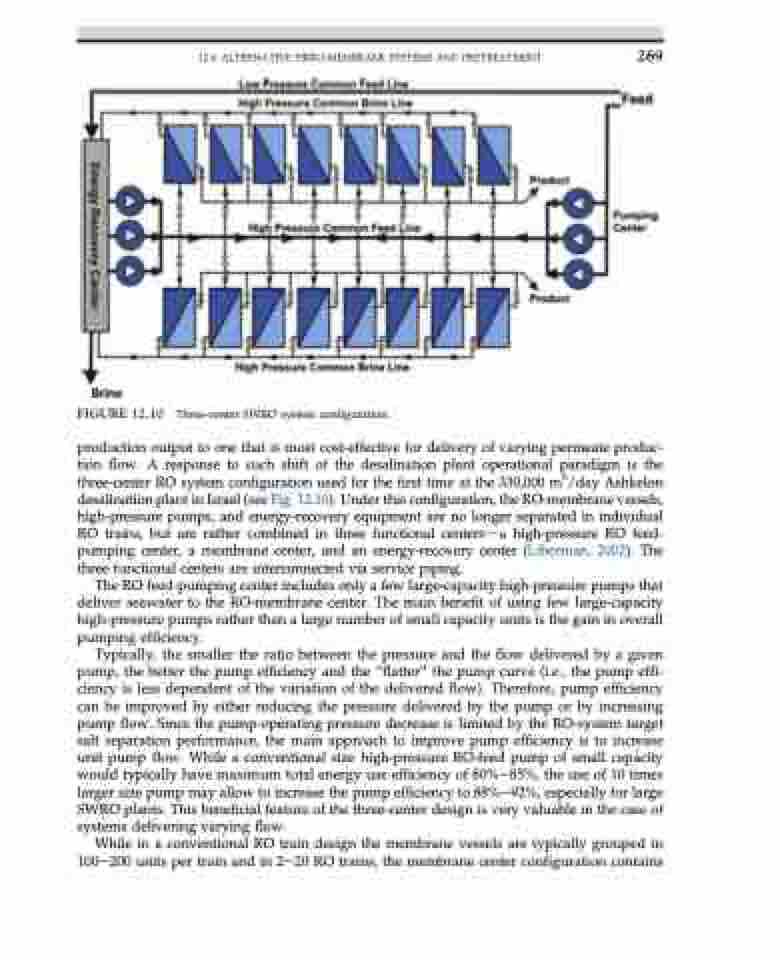
FIGURE 12.10 Three-center SWRO system configuration.
production output to one that is most cost-effective for delivery of varying permeate produc- tion flow. A response to such shift of the desalination plant operational paradigm is the three-center RO system configuration used for the first time at the 330,000 m3/day Ashkelon desalination plant in Israel (see Fig. 12.10). Under this configuration, the RO-membrane vessels, high-pressure pumps, and energy-recovery equipment are no longer separated in individual RO trains, but are rather combined in three functional centersda high-pressure RO feed- pumping center, a membrane center, and an energy-recovery center (Liberman, 2002). The three functional centers are interconnected via service piping.
The RO feed-pumping center includes only a few large-capacity high-pressure pumps that deliver seawater to the RO-membrane center. The main benefit of using few large-capacity high-pressure pumps rather than a large number of small capacity units is the gain in overall pumping efficiency.
Typically, the smaller the ratio between the pressure and the flow delivered by a given pump, the better the pump efficiency and the “flatter” the pump curve (i.e., the pump effi- ciency is less dependent of the variation of the delivered flow). Therefore, pump efficiency can be improved by either reducing the pressure delivered by the pump or by increasing pump flow. Since the pump-operating pressure decrease is limited by the RO-system target salt separation performance, the main approach to improve pump efficiency is to increase unit pump flow. While a conventional size high-pressure RO-feed pump of small capacity would typically have maximum total energy use efficiency of 80%e85%, the use of 10 times larger size pump may allow to increase the pump efficiency to 88%e92%, especially for large SWRO plants. This beneficial feature of the three-center design is very valuable in the case of systems delivering varying flow.
While in a conventional RO train design the membrane vessels are typically grouped in 100e200 units per train and in 2e20 RO trains, the membrane center configuration contains
