
Page 67 - ro membanes
P. 67
50 3. DIAGNOSTICS OF MEMBRANE FOULING AND SCALING
The data from the permeate vessel probing should be interpreted taking into consideration
the following rules of thumb derived from operational experience:
1. Conductivity of the first membrane element in the vessel is typically around two times lower than that of the last membrane element.
2. As probe is moved downstream, the conductivity is expected to increase uniformly.
3. Abrupt increase in conductivity indicates a leak or poorly performing element.
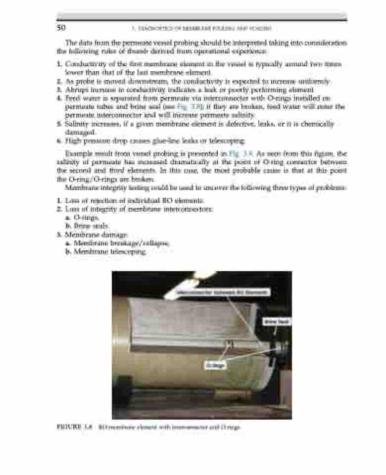
4. Feed water is separated from permeate via interconnector with O-rings installed on
permeate tubes and brine seal (see Fig. 3.8); if they are broken, feed water will enter the
permeate interconnector and will increase permeate salinity.
5. Salinity increases, if a given membrane element is defective, leaks, or it is chemically
damaged.
6. High pressure drop causes glue-line leaks or telescoping.
Example result from vessel probing is presented in Fig. 3.9. As seen from this figure, the
salinity of permeate has increased dramatically at the point of O-ring connector between the second and third elements. In this case, the most probable cause is that at this point the O-ring/O-rings are broken.
Membrane integrity testing could be used to uncover the following three types of problems:
1. Loss of rejection of individual RO elements.
2. Loss of integrity of membrane interconnectors:
a. O-rings,
b. Brine seals.
3. Membrane damage:
a. Membrane breakage/collapse, b. Membrane telescoping.
FIGURE 3.8 RO-membrane element with interconnector and O-rings.
