
Page 84 - Demo
P. 84
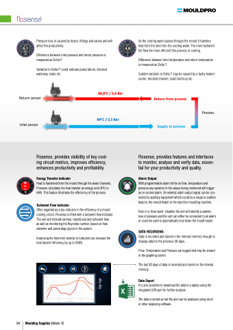
Pressure loss is caused by hoses fittings and and valves and and will As the the cooling water passes through the the mould it it transfers affect the the the productivity heat from the the the steel into the the the cooling water The more turbulent
Difference between inlet pressure pressure and and and return pressure pressure is is Pressure loss is is caused by hoses fittings and and and valves and and and will affect the productivity measured as as Delta Delta P P Difference between inlet temperature temperature and and and return temperature temperature Difference Difference between between inlet inlet pressure pressure and return pressure pressure is is measured measured measured as as as as as as DeltaisP measured measured measured as as as as as as Delta Delta Delta T Variation in in in in Delta Delta P P could could indicate indicate pump pump failure failure blocked
blocked
Variation Variation in in in in Delta Delta P P could could indicate indicate pump pump failure failure blocked
blocked
waterway waterway leaks leaks etc etc the the flow the the more efficient this process of cooling waterway leaks etc Sudden variation in Delta T may be caused by a a a a a a a a faulty heater/ cooler blocked
channel scale build up etc Return sensor
Inlet sensor
88 8°C / 3 4 Bar
84°C / 3 5 Bar
Return from process Supply
to process Process
Cooling water is is transfering heat from the the the the mould mould and the the the the temperature is is increasing on the the the the way through the mould Difference between inlet temperature temperature and and return temperature temperature is is measured as as Delta T Flosense Flosense provides provides visibility of key cool- Flosense Flosense provides provides features and and and interfaces
Alarm Output
With programmable alarm limits on flow temperature and pressure any variation in in the values being monitored will trigger an an on-screen alarm alarm An external alarm alarm output signal can be con- nected to auxiliary equipment which could be a a a a a visual or audible beacon the the mould mould heater or the the injection moulding machine Even in a a a ‘hose burst’ situation the unit will identify a a a sudden loss of pressure and the the unit can either be connected to an an an alarm or could be used to to automatically shut down the mould heater DATA RECORDING
Data is recorded and stored in in the internal memory enough to to display data for the previous 30 days Flow Temperature and and Pressure are logged and and may be viewed in in the graphing screen The last 30 days of data is recorded and stored on the internal memory Data Export
It is also possible to to to download the the data to to to a a a a a a laptop using the the integrated USB port
for further analysis The data is stored as text file and can be analysed using excel or other analysing software Sudden variation in in Delta T may be caused by faulty heater/cooler blocked
channel scale ing circuit metrics improves efficiency Heat is transfered from the the mould through the the water channels 6 5 Flosense calculates the the the heat transfer transfer as energy units BTU or kWh This feature illustrates the the effeciency of the the process Turbolent Flow Indicator
Often regarded as a a a a a key indicator in in the efficiency of a a a a a mould cooling circuit Flosense is fitted with a a turbulent
flow indicator The unit will indicate laminar transitional and turbulent
flow as as as well as as as monitoring the Reynolds number based on on flow diameter and percentage glycol in the system Improving the the flow from laminar to turbulent
can increase the the heat transfer efficiency by up to 500% to to monitor analyse and and and verify data essen- tial for your productivity and and quality enhances productivity and profitability build up etc Energy Transfer Indicator
84 Moulding Supplies Edition 12
