
Page 90 - Demo
P. 90
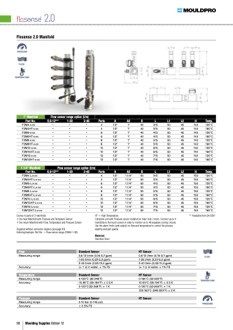
Flosense 2 0 Manifold
1” Manifold
Part No F2M4-x-xx
F2M4HT-x-xx F2M6-x-xx F2M6HT-x-xx F2M8-x-xx F2M8HT-x-xx F2M10-x-xx F2M10HT-x-xx F2M12-x-xx F2M12HT-x-xx
1 1 1/4” Manifold
Part No Flow sensor range option (l/m)
0 0 0 6-12** 1-20 2-40 Ports A A A2 B L
• • • • • • • • • 4 4 1/2" 1" 40 315 • • • • • • • • • 4 4 1/2" 1" 40 315 • • • • • • • • • 6 1/2" 1" 40 415 • • • • • • • • • 6 1/2" 1" 40 415 • • • • • • • • • 8 1/2" 1" 40 515 • • • • • • • • • 8 1/2" 1" 40 515 • • • • • • • • • 10 1/2" 1" 40 615 • • • • • • • • • 10 1/2" 1" 40 615 • • • • • • • • • 12 1/2" 1" 40 715 • • • • • • • • • 12 1/2" 1" 40 715 Flow sensor range option (l/m)
0 0 0 6-12** 1-20 2-40 Ports A A A2 B L
L1 L2
50 45 50 45 50 45 50 45 50 45 50 45 50 45 50 45 50 45 50 45 L1 L2
50 45 50 45 50 45 50 45 50 45 50 45 50 45 50 45 50 45 50 45 H Temp 140 120°C 140 160°C 140 120°C 140 160°C 140 120°C 140 160°C 140 120°C 140 160°C 140 120°C 140 160°C H Temp 150 120°C 150 160°C 150 120°C 150 160°C 150 120°C 150 160°C 150 120°C 150 160°C 150 120°C 150 160°C ** Available from Q4 2021
F2M4-L-x-xx • • • • • • • • • 4 4 4 1/2" 1 1 1 1 1/4" 50 315 F2M4HT-L-x-xx • • • • • • • • • 4 4 4 1/2" 1 1 1 1 1/4" 50 315 F2M6-L-x-xx • • • • • • • • • 6 6 1/2" 1 1 1 1 1/4" 50 415 F2M6HT-L-x-xx • • • • • • • • • 6 6 1/2" 1 1 1 1 1/4" 50 415 F2M8-L-x-xx • • • • • • • • • 8 8 1/2" 1 1 1 1 1/4" 50 515 F2M8HT-L-x-xx • • • • • • • • • 8 8 1/2" 1 1 1 1 1/4" 50 515 F2M10-L-x-xx • • • • • • • • • 10 10 1/2" 1 1 1 1 1 1 1/4" 50 615 F2M10HT-L-x-xx • • • • • • • • • 10 10 1/2" 1 1 1 1 1 1 1/4" 50 615 F2M12-L-x-xx • • • • • • • • • 12 12 1/2" 1 1 1 1 1 1 1/4" 50 715 F2M12HT-L-x-xx • • • • • • • • • 12 12 1/2" 1 1 1 1 1 1 1/4" 50 715 Comes in pairs of 2 manifolds
• One feed Manifold
with Pressure and Tempature Sensor
• One return Manifold
with Flow Temperature and Pressure Sensor
Supplied without connector nipples (see page 93)
Ordering Example: Part No + Flow sensor range (F2M4-1-20)
Flow Measuring range Accuracy
Temperature Measuring range Accuracy
Pressure Measuring range Accuracy
HT = High Temperature Complete unit with Pressure sensor installed on on main inlet / return Connect up to 4 manifolds
to to to to to the touch screen in in order to to to to to monitor uo to to to to to 48 separate cooling circuits Use the the alarm limits (and output) on on flow and and temperature to control the the process stability and part quality 90 Moulding Supplies Edition 12 Material:
Stainless Steel
Standard Sensor
0 0 6-12 I/min (0 16-3 7 gpm) 1-20 I/min (0 27-5 2 2 2 gpm) 2-40 I/min (0 53-10 4 4 gpm) (± 1 1 o) in water ± ± 1% FS
Standard Sensor
0-120°C (32-248°F) 15-90°C (59-194°F) ± 0 0 5 5 5 K 0-120°C(32-248°F) ± 1 1 K Standard Sensor
0-10 bar (0-145 psi) ± 2 5% FS
HT Sensor
0 0 6-12 I/min (0 16-3 7 gpm) 1-20 I/min (0 27-5 2 2 2 gpm) 2-40 I/min (0 53-10 4 4 gpm) (± 1 1 o) in water ± ± 1% FS
HT Sensor
0-160°C (32-320°F)
15-90°C (59-194°F) ± 0 0 5 5 5 K 0-120°C (32-248°F) ± 1 1 K 120-160°C (248-320°F) ± 2 2 2 2 K HT Sensor
