
Page 72 - Gas Detection Systems Training Manual
P. 72
SEC3120 TRANSMITTER INIT MEMORY CARD ...
Success
S1
SENSOR
INIT
ID: XXX / YYY 0-W AITING WAITING
S2
S1 SENSOR ID: XXX / YYY WARMUP 0-WAITING
-ENT- TO WAITING S2 ABORT
S1
SENSOR
UPLOAD
ID: XXX / YYY 0-W AITING
W AITING
S2
7. Normal Operation
‘INIT MEMORY CARD ....’ – Memory card system Initializing.
‘SUCCESS’ or ‘FAILURE’ will show after a few seconds.
‘S1’ or ‘S2’ alternates and identifies that the displayed data is for either Sensor 1 or Sensor 2.
‘ID: XXX’ refers to the user assigned ID for Sensor 1. ‘ID: YYY’ refers to the user assigned ID for Sensor 2.
‘SENSOR WARMUP’ – indicates that the given sensor (S1 or S2) is warming up.
‘SENSOR UPLOAD’ – Sensor is uploading its parameters to The 3120.
In the normal operating mode, the 4-20 mA signal levels correspond to the detected gas concentration. The transmitter continuously checks for and displays system faults or initiation of calibration and automatically changes to the appropriate mode.
The 4-20 mA output ports of the SEC3120 are non-isolated current source(s), passed through from the attached sensor(s). Their output values are defined by the associated sensor manual(s) (4 – 20 mA normal gas levels, less than (<) 4 mA indicates a status condition such as warm-up, calibration or a sensor fault).
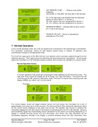
Normal Operation Screen
In normal operating mode actual gas concentration will be displayed on the left of the screen. The right side of the screen will display the ID #, Range, Gas Type and Status. The bottom line will scroll through the MC (memory card) status, Date, Time and, if a sensor has a warning code, will display ‘WARN: xxx’ where ‘xxx’ is a cell code #.
Example:
The normal display screen will toggle between sensor one and sensor two information at a rate of approximately once every two to three seconds. The alarm and fault LEDs indicate the alarm/fault status for the current sensor displayed at any given time as well. The operator may choose to advance the information displayed to the next sensor’s information by selecting either the UP or DN switches. Doing so will immediately toggle the normal display screen information for the sensor not currently displayed (i.e. If display is currently showing sensor one (S1) information, then sensor two (S2) information will be immediately displayed, whereas if the display is currently showing sensor two (S2) information, then
Operator Manual Page 11 of 40 P/N 1580281 SEC3120 Digital Transmitter Sensor Electronics Corporation Rev 10, 20150707
S1 ID: XXX
0 (S1 GAS RANGE)
(S1 GAS TYPE) (STATUS)
ID: YYY
0 (S2 GAS RANGE)
(S2 GAS TYPE) S2 (STATUS)
S1 0 ID:010
0-100 %LEL
METHANE MC - FAULT
0 ID: 011 0-200 PPM
AMMONIA S2 08/15/2010
S1 0 ID:010
0-100 %LEL
METHANE 23:15:33
0 ID: 011 0-200 PPM
AMMONIA S2 WARN: 131
