
Page 83 - Gas Detection Systems Training Manual
P. 83
EJECT MEMORY CARD ABORT WARMUP
INFO
* MAIN MENU
CALIBRATION ALARM RELAY
* NETWORK
* NETWORK ID MENU MODBUS SETTINGS PREVIOUS MENU
* FOR SENSOR: ONE/TWO * ID XXX
ZONE YYY PREVIOUS MENU
FOR SENSOR: ONE/TWO *ID XXX*
ZONE YYY PREVIOUS MENU
FOR SENSOR: ONE/TWO
ID XXX *ZONE YYY*
PREVIOUS MENU
FOR SENSOR: ONE ID 13 ZONE 3
* PREVIOUS MENU
NETWORK ID MENU
MODBUS SETTINGS * PREVIOUS MENU
* SAVE CHANGES ABORT CHANGES
Operator Manual
SEC3120 Digital Transmitter
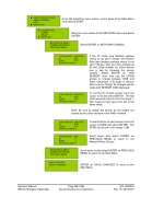
From the Initial/Top menu screen, cursor down to the Main Menu and select ENTER.
Move the cursor down to the NETWORK menu and select ENTER.
Select ENTER on NETWORK ID MENU.
If the ID mode (see Modbus settings menu) is not set to ‘Single’ and Sensor Role (see Modbus settings menu) is not set to ‘Single’, then you may change the ID and Zone number for either sensor one or two by choosing the sensor number. Select ENTER on ‘FOR SENSOR’ item, and use the UP/DN arrows to change between ONE and TWO. Otherwise, if ID mode or Sensor Role is set to ‘Single’ all changes will be made with SENSOR ONE displayed.
To set the ID of each sensor move the cursor to ID and select ENTER. The IDs of the sensors may be set in the range 1- 254, however they cannot be set to the same value.
Note: Be sure to assign the sensor an ID number not shared by any other sensors in the HMI’s network.
To set the Zone of each sensor move the cursor to ZONE and select ENTER. The ZONE can be set in the range 1-254.
Scroll down and select ENTER on PREVIOUS MENU to return to the Network Menu Screen.
Scroll down to and select ENTER on PREVIOUS MENU to return to the Main Menu.
ENTER on ‘SAVE CHANGES’ to return to the Main Menu.
Page 22 of 40 P/N 1580281 Sensor Electronics Corporation Rev 10, 20150707
