
Page 52 - Wilger Catalog
P. 52
M O N I T O R I N G
Wilger Visual Ball Flow Indicators - Balls & Setup Guide
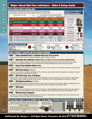
Flow Indicator Balls & Selection Chart
Weighted balls are used inside flow indicator columns and within the operational flow range, will suspend within the column, showing relative flow rate to other flow columns.
Ball Description & Color
Applying Dark Fertilizers & Variable Rate Applications
Part #
Flow Indicator Columns & Flow Ranges*
With more liquid fertilizers and products being darker (e.g humic acid content), consider a few tips that may help visual representation of flow.
Ultra Low Flow
Low Flow
Standard Flow
Orange Polypropylene Ball*
20460-13
0.01-0.04 us gpm
Green Polypropylene Ball*
0.05-0.12 us gpm
0.05-0.12
us gpm
0.07-0.25 us gpm
0.07-0.25
us gpm
For Red Liquids (e.g. Paralign Fertilizer)
White backboard for improved visibility. White celcon ball for red liquids.
20460-08
0.01-0.04
us gpm
Red Celcon Ball*
20460-07
0.02-0.06
us gpm
0.06-0.16
us gpm
0.10-0.35
us gpm
White Celcon Ball*
20460-18
0.02-0.06
us gpm
0.06-0.16
us gpm
0.10-0.35
us gpm
For Dark Liquids (e.g. Humic Acid)
Pink celcon ball for black & dark liquids.
Pink Celcon Ball*
20460-14
0.02-0.06
us gpm
0.06-0.16
us gpm
0.10-0.35
us gpm
Red Glass Ball
20460-06
0.06-0.13
us gpm
0.12-0.26
us gpm
0.21-0.72
us gpm
For Variable Rate Considering using two balls to better illustrate changes in flow rate. Select a lighter ball for the lower rate, and heavier for the higher rate
1/2" Stainless Steel (302) Ball
*Density/Viscosity of liquid used can effect operating range. In very dense liquids, balls may float.
20460-05
0.13-0.24 us gpm
0.18-0.65 us gpm
0.40-1.70 us gpm
7/16" Stainless Steel (302) Ball
20460-10
n/a
n/a
1.00-2.70 us gpm
Ball Selection Example
Liquid Weight: 10.67 lbs/ US Gallon Speed: 5 mph
Outlet Spacing: 30 inch
Ultra-Low Flow Rate: 4.5 US Gal/Acre Flow Rate: 0.129 us gpm Ball: Red Glass
Low Flow Rate: 10 US Gal/Acre
Flow Rate: 0.286 us gpm Ball: 1/2” Stainless
Standard Flow Rate: 20 US Gal/Acre Flow Rate: 0.571 us gpm Ball: Red Glass
Guide to Building a Liquid Kit with Flow Indicator Manifolds
STEP 1 Select: Manifold-Feed or Isolated-Feed Style Flow Columns Choose the style of flow column that suits the application equipment being monitored
STEP 2 Determine Flow Indicator Column Size (e.g. Ultra Low Flow, Low Flow, Standard Flow) Depending on the flow rates required, select the flow column that would provide the best fit to the required flow rate or range.
Usually this is accomplished by finding a column size that has your flow rate towards the middle of the range or higher.
STEP 3 Select: Flow Indicator Balls to use
Consult the ball flow chart to determine which balls should be used. It can be optional to use two balls to illustrate a flow rate range.
STEP 4 ORS Check Valves [Optional]
A variety of check valves are available. Typically an ORS to ORS check valve would be used unless adapting a manifold to combo-jet
caps. One check valve is required per flow indicator.
STEP 5 ORS Inlet Feeds, Tees, & Strainers
Determine how many manifolds are required, whether the manifolds are fed with a Tee fitting, as well as whether an inline strainer
will be added to each manifold. Determine the size & type of inlet fitting. One set of inlet/tee/strainer is required per manifold.
STEP 6 ORS Metering Orifices [Optional]
Any metering manifold should have a means to meter the flow for each row to keep rows consistent. Without a metering orifice, the
flow rates between rows can vary greatly. One metering orifice would be required per flow indicator column.
STEP 7 ORS Outlet
Select the size, and style of outlet to be used for each row of product. Consider applying a small bit of lubricant (e.g. liquid silicone)
on the o-ring to air in easy installation of outlets and other ORS fittings. The outlet would hold the ORS metering orifice, if used.
STEP 8 ORS End Caps & Adapters
A variety of end caps are available as adapters which can be used for many situations, but typical an ORS end cap would be used. Two end caps are required per manifold if a Tee fitting is used.
Do you plant at night or in low visibility? Take a look at Wilger’s Electronic Flow Monitoring (EFM) System
Wilger’s row-by-row flowmeter uses the same ORS parts and manifolds, and can be simply added inline for existing manifolds.
Simply add a flowmeter for each row and connect the electronic harness to see actual flow rate on each row (up to 200 rows), for flow rates of 0.04-1.53 us gpm flow.
Flowmeter can also be installed on flow indicators to provide greater accuracy
52 ©Copyright 2022 Wilger Industries Ltd. Distributed By: Sensor-1 • 202 Main Street, Princeton, KS 66078 • 1-800-SENSOR-1
