
Page 55 - Wilger Catalog
P. 55
Wilger Electronic Flow Monitoring System Components
Single-Sensor Cables (lim. qty)
4 Channel (4CH) Product Node Kits & Components
4 Channel Product Nodes & kits provide communication between sensors and ECU. Sensor cables cannot be interchanged between 16CH and 4CH node harnesses. 4CH nodes and sensors are available in limited stock, as Wilger is transitioning to using the 16CH node and components as standard.
Product Description Part#
Capping Unused Connections
4CH Node Kit
incl. 4CH Node, 4CH Harness, 4x 6” single-sensor cables
20620-00
4CH Node/Harness
incl. 4CH Product Node, 4CH Node Harness
20608-00
For proper function of your EFM system, each unused connection must be sealed
with a 4CH node harness/sensor cover cap, or terminator.
Unused Sensor Connections
Cap unused 4CH node harness connections
#20609-00
Terminators
Cap all ‘last node in series’ connections
#20604-00
4CH Harness Cap
4CH Harness Cover Cap
20609-00
6” single-sensor Cable for 4CH Node harness
20584-00
10’ single-sensor Cable for 4CH Node harness
20584-10
20620-00 4 CHANNEL (4CH) NODE KIT BREAKDOWN
Single Sensor Cables (for 16CH Nodes)
4
3
20608-01
4CH NODE
1 2 3 4
Node Connects to Harness
Connects to next node in series Connects to ECU (or previous node) Connects up to 4 single sensor cables
20584-00
4CH Node connects to up to 4 single sensor cables
1
20608-02
4CH NODE HARNESS
Electronic Flow Monitoring System: Auxiliary Component Parts
Electronic flow monitoring system parts and components are easily replaceable. For individual component parts that were not listed in the above product breakdowns, find the below.
20580-06 20580-01 20580-02 20580-08 20580-10 20580-11 20580-13 20583-00 20585-01
EFM, Body Assy, TPX, ORS (no jets, body assy only) EFM, Body Only, TPX
EFM, Module c/w O-ring (no sensor)
EFM, Impeller Assembly (20580-08 + 20580-10) EFM, Impeller Magnet, Ceramic
EFM, Impeller Axle Pin
EFM, O-Ring, #119, VITON® (for EFM module)
EFM Sensor Cable, Single w/o Connector
EFM sensor rubber cover (for unused sensor cables)
20583-00* *Non-stocked/Custom Order
20585-01
20580-02
20580-11
20580-08
2
!
Cost effectiveness of 4CH nodes: For any configurations requiring more than 2x 4CH node in series for 8+ sensors, it can be more cost effective to have a 16CH node and plug off unused harness connectors.
EFM Retrofit Options
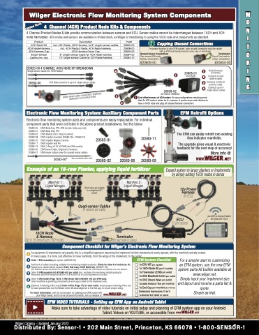
Example of an 16-row Planter, applying liquid fertilizer
Expand system to larger planters or implements
Wilger Catalog - Updated January 2022
55
EFM VIDEO TUTORIALS - Setting up EFM App on Android Tablet
20580-06
Component Checklist for Wilger’s Electronic Flow Monitoring System
! As equipment & implements vary greatly, this is a simplified approach assuming the implement is fairly standard and evenly spread, with the manifold centrally located. In many cases, it is more cost effective to move manifolds, from the wings of the implement, to the center.
1 Order 1 ECU assembly per system. (#20603-00)
Add the # of outlets (including multiples for monitoring multiple products). Divide the total # of outlets by 16.
2 Round up to nearest whole number. Order that many 16CH Node kits. (#20621-00)
4CH Node kits can also be effective for ‘extra’ outlets in systems as needed, but 16CH node kits are typically more cost effective.
3 Order 1 EFM assembly kit (#20580-00) per outlet (incl. multiples for monitoring multiple products) Alternatively, order EFM manifold kits (#20631-00 to #20634-00) to fit your requirements for sections.
4 Order 1 ORS Outlet (Page 16) & 1 ORS Check Valve (#20551-00) per EFM body. Order manifolds & plumbing components (& end caps) suited for the implement size.
5 [Optional if metering orifice req’d] Order orifice (Page 17) for each outlet, ensure proper metering orifice size for each product/rate. Use Tip Wizard online @ www.wilger.net or the free app, to ensure proper sizing.
For more information, start the conversation on building your EFM system with your Wilger dealer, and for more pictures/information, visit our website at:
For a simpler start to customizing
an EFM system, use the new EFM system parts kit builder available at www.wilger.net.
Simply input your implement size and layout and receive a parts list & quote.
Simple as that.
EFM System Checklist
The EFM can easily retrofit into existing flow indicator manifolds.
The upgrade gives visual & electronic feedback for the next step of accuracy!
More info @
by simply adding 16CH nodes in series
M O N I T O R I N G
Manifold 1 Liquid Nitrogen
16CH Node
& Harness
(Up to 16 sensors per 16CH node)
Check valves are available in a straight and 90° version
Quad-sensor Cables
(4 sensors per cable)
Manifold 2 Liquid Nitrogen
Terminator
(for last node in series)
12v Power Harness (to ECU)
ECU
(1 per system)
(via WIFI to Android Tablet) No Data plan req’d
Make sure to take advantage of video tutorials on initial setup and planning of EFM system app on your Android Tablet. Videos on YOUTUBE, or accessible from
1x ECU KIT per system
1x 16CH Node Kit per 16 outlets 1x Flowmeter (EFM) per outlet
1x ORS Manifold Outlet per outlet 1x ORS Check Valve per outlet
1x Inlet Feed or Tee per manifold 1x End Cap per manifold [2x if Tee’d] Extension harnesses if req’d
1x Android 8.0 Tablet or newer
Distributed By: Sensor-1 • 202 Main Street, Princeton, KS 66078 • 1-800-SENSOR-1
Limited Stock
single sensor cable connected to flowmeter (flowmeter not included in kit)
