
Page 1052 - College Physics For AP Courses
P. 1052
1040 Chapter 23 | Electromagnetic Induction, AC Circuits, and Electrical Technologies
���� � ���� (23.20) is the maximum (peak) emf. Note that the frequency of the oscillation is � � ����, and the period is � � �� � � ����.
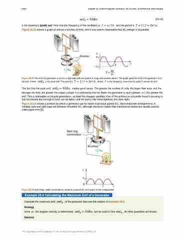
Figure 23.22 shows a graph of emf as a function of time, and it now seems reasonable that AC voltage is sinusoidal.
Figure 23.22 The emf of a generator is sent to a light bulb with the system of rings and brushes shown. The graph gives the emf of the generator as a function of time. ���� is the peak emf. The period is � � � � � � �� � � , where � is the frequency. Note that the script E stands for emf.
The fact that the peak emf, ���� � ���� , makes good sense. The greater the number of coils, the larger their area, and the stronger the field, the greater the output voltage. It is interesting that the faster the generator is spun (greater � ), the greater the
emf. This is noticeable on bicycle generators—at least the cheaper varieties. One of the authors as a juvenile found it amusing to ride his bicycle fast enough to burn out his lights, until he had to ride home lightless one dark night.
Figure 23.23 shows a scheme by which a generator can be made to produce pulsed DC. More elaborate arrangements of multiple coils and split rings can produce smoother DC, although electronic rather than mechanical means are usually used to make ripple-free DC.
Figure 23.23 Split rings, called commutators, produce a pulsed DC emf output in this configuration.
Example 23.4 Calculating the Maximum Emf of a Generator
Calculate the maximum emf, ���� , of the generator that was the subject of Example 23.3. Strategy
Once � , the angular velocity, is determined, ���� � ���� can be used to find ���� . All other quantities are known. Solution
This OpenStax book is available for free at http://cnx.org/content/col11844/1.14
