
Page 892 - College Physics For AP Courses
P. 892
880 Chapter 20 | Electric Current, Resistance, and Ohm's Law
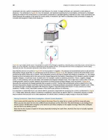
Schematics are very useful in visualizing the main features of a circuit. A single schematic can represent a wide variety of situations. The schematic in Figure 20.3 (b), for example, can represent anything from a truck battery connected to a headlight lighting the street in front of the truck to a small battery connected to a penlight lighting a keyhole in a door. Such schematics are useful because the analysis is the same for a wide variety of situations. We need to understand a few schematics to apply the concepts and analysis to many more situations.
Figure 20.3 (a) A simple electric circuit. A closed path for current to flow through is supplied by conducting wires connecting a load to the terminals of a battery. (b) In this schematic, the battery is represented by the two parallel red lines, conducting wires are shown as straight lines, and the zigzag represents the load. The schematic represents a wide variety of similar circuits.
Note that the direction of current in Figure 20.3 is from positive to negative. The direction of conventional current is the direction that positive charge would flow. In a single loop circuit (as shown in Figure 20.3), the value for current at all points of the circuit should be the same if there are no losses. This is because current is the flow of charge and charge is conserved, i.e., the charge flowing out from the battery will be the same as the charge flowing into the battery. Depending on the situation, positive charges, negative charges, or both may move. In metal wires, for example, current is carried by electrons—that is, negative charges move. In ionic solutions, such as salt water, both positive and negative charges move. This is also true in nerve cells. A Van de Graaff generator used for nuclear research can produce a current of pure positive charges, such as protons. Figure 20.4 illustrates the movement of charged particles that compose a current. The fact that conventional current is taken to be in the direction that positive charge would flow can be traced back to American politician and scientist Benjamin Franklin in the 1700s. He named the type of charge associated with electrons negative, long before they were known to carry current in so many situations. Franklin, in fact, was totally unaware of the small-scale structure of electricity.
It is important to realize that there is an electric field in conductors responsible for producing the current, as illustrated in Figure 20.4. Unlike static electricity, where a conductor in equilibrium cannot have an electric field in it, conductors carrying a current have an electric field and are not in static equilibrium. An electric field is needed to supply energy to move the charges.
Making Connections: Take-Home Investigation—Electric Current Illustration
Find a straw and little peas that can move freely in the straw. Place the straw flat on a table and fill the straw with peas. When you pop one pea in at one end, a different pea should pop out the other end. This demonstration is an analogy for an electric current. Identify what compares to the electrons and what compares to the supply of energy. What other analogies can you find for an electric current?
Note that the flow of peas is based on the peas physically bumping into each other; electrons flow due to mutually repulsive electrostatic forces.
This OpenStax book is available for free at http://cnx.org/content/col11844/1.14
