
Page 4 - Demo
P. 4
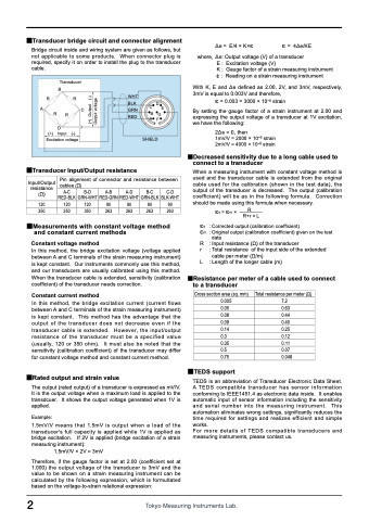
 ■Transducer bridge circuit and connector alignment
Bridge circuit inside and wiring system are given as follows, but not applicable to some products. When connector plug is required, specify it on order to install the plug to the transducer cable.
Δe = E/4 × K×ɛ ɛ = 4Δe/KE
where, Δe: Output voltage (V) of a transducer E : Excitation voltage (V)
K : Gauge factor of a strain measuring instrument ɛ : Reading on a strain measuring instrument
With K, E and Δe defined as 2.00, 2V, and 3mV, respectively, 3mV is equal to 0.003V and therefore,
ɛ = 0.003 = 3000 × 10-6 strain
By setting the gauge factor of a strain instrument at 2.00 and expressing the output voltage of a transducer at 1V excitation, we have the following:
2Δe = ɛ, then
1mV/V = 2000 × 10-6 strain 2mV/V = 4000 × 10-6 strain
■Decreased sensitivity due to a long cable used to connect to a transducer
When a measuring instrument with constant voltage method is used and the transducer cable is extended from the original cable used for the calibration (shown in the test data), the output of the transducer is decreased. The output (calibration coefficient) will be as in the following formula. Correction should be made using this formula when necessary.
ɛs = ɛm × R R+r × L
ɛs : Corrected output (calibration coefficient)
ɛm : Original output (calibration coefficient) given on the test
data
R : Input resistance (Ω) of the transducer
r : Total resistance of the input side of the extended
cable per meter (Ω/m)
L : Length of the longer cable (m)
■Resistance per meter of a cable used to connect to a transducer
  Transducer B
RR
A
R
D
(+) Input (-)
Excitation voltage
  C R
WHT
BLK CDE GRN BG RED AF
SHIELD
     ■Transducer Input/Output resistance
Input/Output Pin alignment of connector and resistance between
 cables (Ω)
A-C B-D A-B A-D B-C C-D
resistance (Ω)
■Measurements with constant voltage method and constant current methods
Constant voltage method
In this method, the bridge excitation voltage (voltage applied between A and C terminals of the strain measuring instrument) is kept constant. Our instruments commonly use this method, and our transducers are usually calibrated using this method. When the transducer cable is extended, sensitivity (calibration coefficient) of the transducer needs correction.
Constant current method
In this method, the bridge excitation current (current flows between A and C terminals of the strain measuring instrument) is kept constant. This method has the advantage that the output of the transducer does not decrease even if the transducer cable is extended. However, the input/output resistance of the transducer must be a specified value (usually, 120 or 350 ohm). It must also be noted that the sensitivity (calibration coefficient) of the transducer may differ for constant voltage method and constant current method.
■Rated output and strain value
The output (rated output) of a transducer is expressed as mV/V. It is the output voltage when a maximum load is applied to the transdcuer. It shows the output voltage generated when 1V is applied.
Example:
1.5mV/V means that 1.5mV is output when a load of the transducer's full capacity is applied while 1V is applied as bridge excitation. If 2V is applied (bridge excitation of a strain measuring instrument):
1.5mV/V × 2V = 3mV
Therefore, if the gauge factor is set at 2.00 (coefficient set at 1.000) the output voltage of the transducer is 3mV and the value to be shown on a strain measuring instrument can be calculated by the following expression, which is formultated based on the voltage-to-strain relational expression:
 RED-BLK GRN-WHT RED-GRN RED-WHT GRN-BLK BLK-WHT 120 120 120 90 90 90 90 350 350 350 263 263 263 263
    Cross section area (sq. mm) 0.005
0.05 0.08 0.09 0.14 0.3 0.35 0.5 0.75
■TEDS support
Total resistance per meter (Ω) 7.2
0.63
0.44 0.40 0.25 0.12 0.11 0.07 0.048
           2
TEDS is an abbreviation of Transducer Electronic Data Sheet. A TEDS compatible transducer has sensor information conforming to IEEE1451.4 as electronic data inside. It enables automatic input of sensor information including the sensitivity and serial number into the measuring instrument. This automation eliminates wrong settings, significantly reduces the time required for settings and realizes efficient and simple works.
For more details of TEDS compatible transducers and measuring instruments, please contact us.
 (+) Output (-) Output voltage
