
Page 82 - Demo
P. 82
Internal strain of concrete, synthetic resin
KM Strain Transducers
Civil engineering design
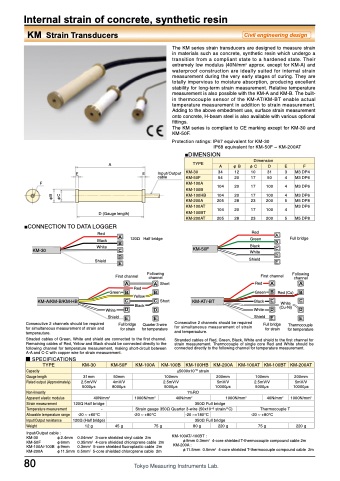
The KM series strain transducers are designed to measure strain in materials such as concrete, synthetic resin which undergo a transition from a compliant state to a hardened state. Their extremely low modulus (40N/mm2 approx. except for KM-A) and waterproof construction are ideally suited for internal strain measurement during the very early stages of curing. They are totally impervious to moisture absorption, producing excellent stability for long-term strain measurement. Relative temperature measurement is also possible with the KM-A and KM-B. The built- in thermocouple sensor of the KM-AT/KM-BT enable actual temperature measurement in addition to strain measurement. Adding to the above embedment use, surface strain measurement onto concrete, H-beam steel is also available with various optional fittings.
The KM series is compliant to CE marking except for KM-30 and KM-50F.
Protection ratings: IP67 equivalent for KM-30
IP68 equivalent for KM-50F ~ KM-200AT
TYPE
Dimension
A
φB
φC
D
E
F
KM-30
34
12
10
31
3
M3 DP4
KM-50F
54
20
17
50
4
M3 DP6
KM-100A KM-100B
104
20
17
100
4
M3 DP6
KM-100HB
104
20
17
100
4
M3 DP6
KM-200A
205
28
23
200
5
M5 DP8
KM-100AT KM-100BT
104
20
17
100
4
M3 DP6
KM-200AT
205
28
23
200
5
M5 DP8
A
■DIMENSION Input/Output
EE
F
cable
Half bridge
Following channel
■CONNECTION TO DATA LOGGER Red A
120Ω
Red A
Full bridge
Following channel
D (Gauge length)
Black B White C
Green
KM-50F Black White
B C D E
KM-30
KM-A/KM-B/KM-HB
Consecutive 2 channels should be required for simultaneous measurement of strain and temperauture.
Shield DE
First channel
Shield
Green
B Yellow B C Black C
A Green B Red(Cu) B
ARed AShort
First channel RedA
Short
KM-AT/-BT
Black C White D
White C (Cu-Ni) D
Straded cables of Green, White and shield are connected to the first channel. Remaining cables of Red, Yellow and Black should be connected directly to the following channel for temperature measurement, making short-circuit between A-A and C-C with copper wire for strain measurement.
■ SPECIFICATIONS
Stranded cables of Red, Green, Black, White and shield to the first channel for strain measurement. Thermocouple of single core Red and White should be connected directly to the following channel for temperature measurement.
80
White D D
Shield
EE
Consecutive 2 channels should be required Shield E
for simultaneous measurement of strain Full bridge
and temperauture.
E
Thermocouple for temperature
Full bridge for strain
Quarter 3-wire for temperature
for strain
TYPE
KM-30
KM-50F
KM-100A
KM-100B
KM-100HB
KM-200A
KM-100AT
KM-100BT
KM-200AT
Capacity
±5000x10-6 strain
Gauge length
31mm
50mm
100mm
200mm
100mm
200mm
Rated output (Approximately)
2.5mV/V 5000μɛ
4mV/V 8000μɛ
2.5mV/V 5000μɛ
5mV/V 10000μɛ
2.5mV/V 5000μɛ
5mV/V 10000μɛ
Non-linearity
1%RO
Apparent elastic modulus
40N/mm2
1000N/mm2
40N/mm2
1000N/mm2
40N/mm2
1000N/mm2
Strain measurement
120Ω Half bridge
350Ω Full bridge
Temperature measurement
-
Strain gauge 350Ω Quarter 3-wire (50x10-6 strain/°C)
Thermocouple T
Allowable temperature range
-20 ~ +60°C
-20 ~ +80°C
-20 ~+180°C
-20 ~ +80°C
Input/Output resistance
120Ω (Half bridge)
350Ω Full bridge
Weight
12 g
45 g
75 g
80 g
220 g
75 g
220 g
Input/Output cable :
KM-30 φ2.4mm
KM-50F φ6mm
KM-100A/-100B φ9mm
KM-200A φ11.5mm 0.5mm2 5-core shielded chloroprene cable 2m
KM-100AT/-100BT :
φ9mm 0.3mm2 4-core shielded T-thermocouple compound cable 2m
KM-200A :
φ11.5mm 0.5mm2 4-core shielded T-thermocouple compound cable 2m
2
0.04mm2 3-core shielded vinyl cable 2m
0.35mm 4-core shielded chloroprene cable 2m 0.3mm2 5-core shielded fluoroplastic cable 2m
φB φC
