
Page 903 - (A) Mammoth (998pp)
P. 903
This report is based on the model forms shown in Appendix 6 of BS 7671
Published by NICEIC, a part of the Ascertiva Group Copyright The Electrical Safety Council (July 2011)
This report is not valid if the serial number has been defaced or altered
IPN3/0385688
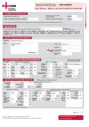
ELECTRICAL INSTALLATION CONDITION REPORT
H. SCHEDULES AND ADDITIONAL PAGES
InspectionSchedule: Page(s)No4,5,6 Additionalpages,includingadditional PageNo(s) source(s) data sheets:
ScheduleofCircuitDetailsfortheInstallation: PageNo(s) 7 ScheduleofTestResultsfortheInstallation: PageNo(s) The pages identified are an essential part of this report. The report is valid only if accompanied by all the schedules and additional pages identified above.
á
N/A
N/A
N/A
N/A
N/A
N/A
8
I. NEXT INSPECTION
I/We recommend that this installation is further inspected and tested after an interval of not more tha1n year
(Enter interval in terms of)
years, months or weeks, as appropriate)
provided that any items at F which have been attributed a Classification code C1 (danger present) are remedied immediately and that any items which have been attributed a code C2 (potentially dangerous) or require further investigation are remedied or investigated respectively as a matter of urgency. Items which have been attributed a Classification code C3 should be improved as soon as practicable (see F).
J. DETAILS OF NICEIC APPROVED CONTRACTOR
Trading Title: Address:
BES Electrical Contractors Ltd
r/o 40-41 Lichfield Road LONDON
Telephone number:
Email Address:
Enrolement number: (Essential information)
Branch number: (if applicable)
0845 094 1717
020073
K. SUPPLY CHARACTERISTICS AND EARTHING ARRANGEMENTS
Postcode:NW2 2RG
System Type(s)
TN-S TN-C-S TN-C TT IT
Number and Type of Live Conductors
Nature of Supply Parameters
Characteristics of Primary Supply Overcurrent Protective Device(s)
BS(EN) BS 88 Fuse HRC gG(General
Nominal Uþ 230 Voltage(s):
Nominal 50 frequency, fþ
Prospective fault current, IÙÄÅ 2.88
V Hz kA
UÒþ
230
V
a.c. á 1-phase á
(2 wire)
(3 wire) Other
1-phase (3 wire)
d.c. N/A 2 pole 3 pole other
Notes:
(1) by enquiry
(2) by enquiry or by measurement
(3) where more than one supply, record the higher or highest values
(4) by measurement
Type
2
Rated current 100
Short-circuit capacity
2-phase (3 wire)
N/A 3-phase N/A
3-phase N/A (4 wire)
N/A
External earth fault loop impendance, Ñ ÄÅ
Number of sources
0.08 É 1
A kA
33
Confirmation of supply polarity
(á)
á
L. PARTICULARS OF INSTALLATION AT THE ORIGIN
Means of Earthing
Distributor's facility:
Installation earth electrode:
Type: (eg rod(s),tape etc)
Electrode resistance, RÕ:
Tick boxes and enter details, as appropriate
Details of Installation Earth Electrode (where applicable)
Location:
(É) Method of measurement:
á
N/A
Main Switch or Circuit-Breaker
Earthing and protective bonding conductors
Earthing conductor
Main protective bonding conductors
Conductor material
Oil csa mmâ service
Bonding of extraneous-conductive-parts (á)
Gas Service
Structural steel
Other incoming service(s)
Type: 60439-3 BS(EN)
No of
Poles 2
Primary supply conductors Copper material
Primary supply conductors 16 csa
Voltage rating
Rated current,IÐ
RCD operating current,IÜ *
230 100
V Conductor material
Conductor A csa
Connection/ mA continuity
Water service
á
á
Copper
Copper
10
Conductor
10
N/A
N/A
* (applicable only where an RCD is suitable and is used as a main circuit-breaker)
mmâ
ms
ms
RCD operating time(atIÜ )*
á
(á)
Connection/ mmâ continuity
verified
(á)
Lightning protection
Specify
á
N/A
N/A
Rated time delay
verified
Page 3 of 8
Please see the 'Notes for Recipients' on the reverse of this page
Original (To the person ordering the work)
