
Page 42 - Ei Electronics Product Selector Guide 2022
P. 42
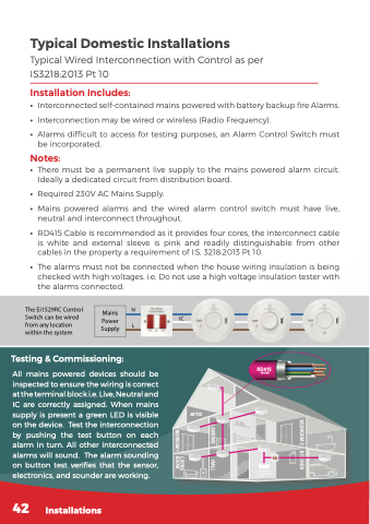
Typical Domestic Installations
Typical Wired Interconnection with Control as per IS3218:2013 Pt 10
Installation Includes:
• Interconnectedself-containedmainspoweredwithbatterybackupfireAlarms.
• Interconnection may be wired or wireless (Radio Frequency).
• Alarms difficult to access for testing purposes, an Alarm Control Switch must be incorporated.
Notes:
• There must be a permanent live supply to the mains powered alarm circuit. Ideally a dedicated circuit from distribution board.
• Required 230V AC Mains Supply.
• Mains powered alarms and the wired alarm control switch must have live,
neutral and interconnect throughout.
• RD415 Cable is recommended as it provides four cores, the interconnect cable is white and external sleeve is pink and readily distinguishable from other cables in the property a requirement of I.S. 3218:2013 Pt 10.
• The alarms must not be connected when the house wiring insulation is being checked with high voltages. i.e. Do not use a high voltage insulation tester with the alarms connected.
     The Ei1529RC Control N Switch can be wired
from any location L within the system
IC
  Mains Power Supply
    Testing & Commissioning:
All mains powered devices should be inspected to ensure the wiring is correct at the terminal block i.e. Live, Neutral and IC are correctly assigned. When mains supply is present a green LED is visible on the device. Test the interconnection by pushing the test button on each alarm in turn. All other interconnected alarms will sound. The alarm sounding on button test verifies that the sensor, electronics, and sounder are working.
  RD415 NHXMH
Connection to Distribution Board
              42 Installations
 ATTIC
