
Page 29 - US Catalog May 2024_V3 PRINT
P. 29
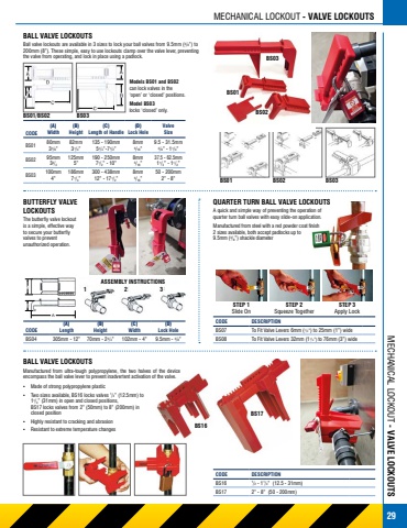
 BALL VALVE LOCKOUTS
Ball valve lockouts are available in 3 sizes to lock your ball valves from 9.5mm (3/8”) to 200mm (8”). These simple, easy to use lockouts clamp over the valve lever, preventing the valve from operating, and lock in place using a padlock.
MECHANICAL LOCKOUT - VALVE LOCKOUTS BS03
BS01/BS02
(A)
BS03
Models BS01 and BS02
can lock valves in the ‘open’ or ‘closed’ positions.
Model BS03
locks ‘closed’ only.
BS01
BS02
BS01
CODE
BS01R
BS02R
BS03R
Width
80mm 31/6”
95mm 33/4
100mm 4”
(B)
Height
82mm 31/4”
125mm 5”
186mm 71/4”
(C)
Length of Handle
135 - 190mm 51/4”-71/2”
190 - 250mm 71/2” - 10”
300 - 438mm 12” - 171/2”
(D)
Lock Hole
8mm 5/16”
8mm 5/16”
8mm 5/16”
Valve Size
9.5 - 31.5mm 3/8” - 11/4”
37.5 - 62.5mm 11/2” - 11/2”
50 - 200mm 2” - 8”
BS02 BS03
BUTTERFLY VALVE LOCKOUTS
QUARTER TURN BALL VALVE LOCKOUTS
A quick and simple way of preventing the operation of quarter turn ball valves with easy slide-on application.
Manufactured from steel with a red powder coat finish 2 sizes available, both accept padlocks up to
9.5mm (3/8”) shackle diameter
The butterfly valve lockout is a simple, effective way to secure your butterfly valves to prevent unauthorized operation.
CODE
BS04R
Lock Hole BS07
9.5mm - 3/8” BS08
To Fit Valve Levers 6mm (1/4”) to 25mm (1”) wide
To Fit Valve Levers 32mm (11/4”) to 76mm (3”) wide
(A)
Length
305mm - 12”
(B)
Height
70mm - 23/4”
(C)
Width
102mm - 4”
(D)
CODE
BALL VALVE LOCKOUTS
ASSEMBLY INSTRUCTIONS 123
Manufactured from ultra-tough polypropylene, the two halves of the device encompass the ball valve lever to prevent inadvertent activation of the valve.
▪ Made of strong polypropylene plastic
▪ Two sizes available, BS16 locks valves 1/2” (12.5mm) to 11/4” (31mm) in open and closed positions, BS17 locks valves from 2” (50mm) to 8” (200mm) in closed position
▪ Highly resistant to cracking and abrasion
▪ Resistant to extreme temperature changes
BS16
DESCRIPTION
1/2 - 11/4” (12.5 - 31mm)
2” - 8” (50 - 200mm)
BS17
CODE
BS16R
BS17R
STEP 1
Slide On
STEP 2
Squeeze Together
DESCRIPTION
STEP 3
Apply Lock
                                    MECHANICAL LOCKOUT - VALVE LOCKOUTS
                         29
