
Page 581 - CAT4
P. 581
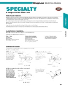
SPECIALTY
Compression Riveters
PRINCIPLES OF OPERATION
Air powered compression riveters deliver a squeezing action, which drives the rivet by “flowing” the rivet metal with compressed forces. Squeezing action is obtained by coupling an air cylinder and piston to a wedge or cam, thus multiplying the original force to extreme ratios. High compressive forces are obtained from a relatively compact unit having small diameter cylinders and using very little compressed air.
The advantage of squeeze riveting is simple sounds of air exhaust and forward piston movement developing tremendous pressures being exerted at the work point.
Optimum control may be obtained in compression riveting. The rivet head is formed by a steady, uniform squeeze action. The set plunger and dolly are an integral part of the squeezer itself.
Length of the return stoke may be adjusted that the plunger itself does not have to travel its full length.
Consistently applied pressure makes for a better appearance of the finished product as well as giving the ultimate in structural efficiency.
CLASSIFICATION OF SQUEEZERS:
Alligator: The squeezing action of the jaws are similar to the movement of an Alligators jaws. ‘C’ Type: The rivet is squeezed between the two ends of the ‘C’.
Type of Rivet:
Rivet material.
Rivet body diameter.
Rivet length before and after compression. Force required to compress rivet.
COMPRESSION RIVETERS
For maximum power the combined length of the two rivet sets must be of the correct length.
Riveter Selection Guide:
What material is the rivet made from? What size is the rivet?
What is the form of the head?
What components are being assembled? Are there any clearance problems?
Is Alligator or ‘C’ type yoke required? How is the application being done now? Are there any special considerations?
Determine the correct lengths as follows:
1) When two cupped rivet sets are used:
3) When two flush sets are used:
The length of the body dimensions of the two rivet sets (A1, A2) should equal the closed height dimension of the yoke (H) minus the total thickness of material being riveted together.
The length of the body
dimensions of the two rivet
sets (A1, A2) should equal the
closed height dimension of the
yoke (H) minus the overall length
of the rivet (M) after it is
compressed. H
cupped rivet set A1
A2 cupped rivet set
flush rivet set
A1 M
M
A1 + A2 = H - M
H
2) When one cupped set and one flush set are used:
If necessary, select rivet sets a little short and shim to the correct length using spacer shims.
A2 flush rivet set
Shim Rivet Set
A1 + A2 = H - L
C-Yoke (or Jaw)
The length of the body dimensions of the two rivet
sets (A1, A2) should equal
the closed height dimension
of the yoke H minus the total thickness of material being riveted (M) and the height of the finished rivet head (Z) compressed by the flush set (A).
cupped rivet set A1
M
Z
H
A2 flush rivet set
A1 + A2 = H - M - Z
581
POWER TOOLS SPECIALTY
