
Page 231 - Nicolaes Witsen & Shipbuilding in the Dutch Golden Age
P. 231
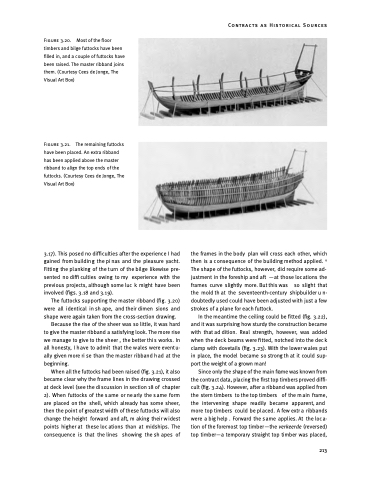
Figure 3.20. Most of the floor timbers and bilge futtocks have been filled in, and a couple of futtocks have been raised. The master ribband joins them. (Courtesy Cees de Jonge, The Visual Art Box)
Figure 3.21. The remaining futtocks have been placed. An extra ribband has been applied above the master ribband to align the top ends of the futtocks. (Courtesy Cees de Jonge, The Visual Art Box)
3.17). This posed no difficulties after the experience I had gained from buildin g the pi nas and the pleasure yacht. Fitting the pl anking of the t urn of the bil ge likewise pre- sented no diffi culties owing to my experience with the previous projects, although some luc k might have been involved (figs. 3.18 and 3.19).
The futtocks supporting the master ribband (fig. 3.20) were all identical in sh ape, and their dimen sions and shape were again taken from the cross-section drawing.
Because the rise of the sheer was so little, it was hard to give the master ribband a satisfying look. The more rise we manage to give to the sheer , the better thi s works. In all honesty, I h ave to admit that the w ales were event u- ally given more ri se than the m aster ribband h ad at the beginning.
When all the futtocks had been raised (fig. 3.21), it also became clear why the frame lines in the drawing crossed at deck level (see the di scussion in section 18 of chapter 2). When futtocks of the s ame or ne arly the s ame form are placed on the shell, which already has some sheer, then the point of greatest width of these futtocks will also change the height forward and aft, m aking their w idest points higher at these loc ations than at midships. The consequence is that the lines showing the sh apes of
the frames in the body plan will cross each other, which then is a c onsequence of the building method applied. 6 The shape of the futtocks, however, did require some ad- justment in the foreship and aft —at those locations the frames curve slightly more. But this was so slight that the mold th at the seventeenth-century shipbuilder u n- doubtedly used could have been adjusted with just a few strokes of a plane for each futtock.
In the meantime the ceiling could be fitted (fig. 3.22), and it was surprising how sturdy the construction became with that ad dition. Real strength, however, was added when the deck beams were fitted, notched into the deck clamp with dovetails (fig. 3.23). With the lower w ales put in place, the model became so strong th at it could sup- port the weight of a grown man!
Since only the shape of the main frame was known from the contract data, placing the first top timbers proved diffi- cult (fig. 3.24). However, after a ribband was applied from the stern timbers to the top timbers of the m ain frame, the intervening shape readily became apparent, and more top timbers could be pl aced. A few extr a ribbands were a big help . Forward the s ame applies. At the loc a- tion of the foremost top timber—the verkeerde (reversed) top timber—a temporary straight top timber was placed,
Contracts as Historical Sources
  213
