
Page 234 - Nicolaes Witsen & Shipbuilding in the Dutch Golden Age
P. 234
Chapter Three
holding the ribband while the fi nal shape was being es- tablished. More and more top timbers were placed, their shape derived as much as possible from the neighboring timbers (fig. 3.25). Applying a ribband for e ach hance is recommended, as was done on full- size ships. I disc ov- ered this rather late, which meant a lot of extra work (see the final position of the hances in fig. 3.26). At this stage the ship was launched and the shaping of the hull was completed.
Readers can judge the suc cess of the experiment from the photogr aphs of the fi nal result (figs. 3.27 and 3.28). The model has some original features of the Dutch shell-first method: the straight rise of the floor; the angu- lar bilges; the thorough ly disguised traces of the cle ats and the arbitr arily positioned ends of the fr ame timbers; and the timbers joined together only by the pl anks and the ceilings, not directly to one another . The model was built almost entirely without plans and in less than 1,000 construction hours.
Sample Contracts
This section consists of various contracts for a number of ship types of Witsen’s time. They all deal with vessels that were specified no further than “ships,” which referred to three- masted, square-sterned vessels. I h ave grouped these sample contracts according to their m ain focus— hulls, masts and spars, rigging, b locks, and s ails—and have added c omments and s imple drawings illustrating contract specifications if the c ontract offered suffi cient data for suc h a dr awing. The absence of a dr awing for
a particular contract does not mean that the document lacks sufficient data for constructing a model, however.
Contracts for Hulls
The following c ontract has a legal c haracter, although it contains many dimensions as well. The length of the ship is given as 125 feet, but that might be a slip of the pen, as most of the dimen sions given would indic ate a muc h larger ship—of at least 160 feet. It also has an orlop deck, which was normally a feature of big ships only. The heavy construction called for in the c ontract gives reason to be- lieve that th is ship was a m an-of-war, so the orlop dec k mentioned here would h ave had a muc h more dec ided function: providing space for the g alley, sail and shot lockers, workshops for s ailmakers and c arpenters, and so on. In merc hantmen the orlop dec k changed depend- ing on the load. The heavy construction is seen in the fact that each deck beam was to be provided w ith a futtoc k rider, complete with hold and bilge riders. In contrast, the pinas had only one futtock rider between each pair of gun- ports and hold and bilge riders only at the location of the mainmast.
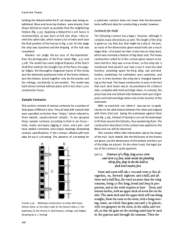
With so many futt ock riders it was eas ier to apply chocks on the deck beams between the riders and aligned with them, then just laying the w aterways against them (see fig. 3.29), instead of having to cut out the waterways to fit them around the futtocks, thus weakening them. The construction described in this contract was applied on the Wasa and can still be observed.
This contract offers little information about the shape of the hul l. Such details like the thic kness of the fr ames are given; yet the dimensions of the bottom and the t urn of the bilge are absent. On the other h and, the legal sta- tus of the contract is quite apparent.
(98 II 5) Contract of a Ship, long across stem and stern 125 feet, wide inside the planking
thirty feet, deep in the the hold at deck level twelve feet.
Stem and stern will rak e two and twen ty feet al- together, or, forward eighteen and a half, and aft three and a half feet, for ward no more than the wing transom, being 20 feet long, broad and deep in pro- portion, and as the work requires at least fteen, and sixteen inches, with an upper deck of seven feet in the side. The main deck and the upper deck will run along straight, from the stem to the stern, with a long steer- ing stand, on w hich four guns can easil y be placed , with two gunports in the stern, in the cabin, and two aft, so that the guns on the steering stand may be used in the quarters and through the transom. Then the
Figure 3.29.
futtock riders: A, the ship’s wall; B, the futtock riders; C, the waterway; D, the chocks; E, deck beams, carlings, and ledges. (Drawing by A. J. Hoving)
216
Waterway construction on ships with many
