
Page 29 - Nicolaes Witsen & Shipbuilding in the Dutch Golden Age
P. 29
he describes are not ably higher th an they appear to be in Witsen’s text, being “three and a half feet, for ward a little less, aft some more, to facilitate working underneath the hull.”13 Witsen does not describe the stocks, but from illustrations such as II.45 and II.4 6 it is apparent that he pictured them lower. The reason for this difference can be found in Van Yk’s statement about working under the hull: with Witsen’s method working underneath the floor is not necessary, and for c aulking the ship i s laid on its side, whereas with Van Yk’s method the planking is fastened to the frames at a much later stage, as we will see.
Both building methods are identical up to the r aising of the stem and sternpost and the application of the gar- board strake, the first plank next to the keel. Witsen then continues with the rest of the pl anking of the lower hul l, but Van Yk first raises two c omplete frames on prec isely determined places on the keel. Between these two frames the shape of the hull is uniform. We will discuss how these frames are shaped later.
A master ribband (scheerstrook) is then fixed to poles, which the master ship wright has raised around the outer shape of the hull. This temporary ribband determines the height of the m aximum width of the ship . Witsen also mentions this master ribband, but for Van Yk it is much more important, as it already shows something of the shape of the hull.
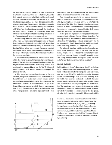
A third frame is then raised on the sc arf of the stem and keel, being more or less identical to both main frames but a little sm aller, as the hul l narrows forward and af t and the frame is raised a little higher than the others. The shape of the aft frame is deduced from the sh ape of the forward frame, a process for which there is a simple rule (see fig. 1.6). The aft frame is placed as far from the back of the sternpost as the fore frame is placed from the front
of the stem. Thus, according to Van Yk, the shipbuilder is able to determine the exact trim by the stern.
Then ribbands areappliedfr om stemtosternpost over the four fr ames. The master shipbuilder models his ship by moving these ribbands until he i s satisfied with the shape of the ship. Then the rest of the frames are po- sitioned in the ba sket of ribbands, br aced and pl anked internally and supported by shores. Next the deck beams are fitted, and finally the outside is planked.14
All this gives the impression of being a somewhat more advanced method th an the one Witsen describes. Yet nothing indicates that one c ould have evolved from the other. One of the building c ontracts presented b y Van Yk as an ex ample, clearly based on hi s building method, dates from 1629, evidence of a respectable age.
The origin of Van Yk’s building method rem ains un- clear. Some vocabulary, such as the word cent for “rib- band,” might point to contacts with Iberian shipbuilders (cf. cintas, meaning “master ribband”), possibly before and during the Eighty Years’ War against Spain. But I can- not offer any definitive answer to this question.15
English Methods
In his edition of Deane’s Doctrine on Naval Ar chitecture, Brian Lavery makes some int eresting points. As in Hol- land, contract specifications in Engl and were custom ary, and not every shipwright worked from dr afts. A sy stem called “whole molding” was practiced, whereby mas- ter molds were used to c onstruct the hull with the same curves over the whole leng th. Even today wooden sloops and boats are built this way in Engl and and Nor th Amer- ica. The results are e asy for exper ts to rec ognize, as the shape in the bow and stern i s not ideal. Deane, however, reveals that members of a sm all group of top des igners, all using drafts, applied curves with different radii, which
Figure 1.6. Construction of Van Yk’s aft frame. Left: The fore
frame, its centerline indicated by X. Right: The aft frame. The
waterlines are drawn as a –b , c –d , and e –f , increasing 1111 11
in height by as much as the ship sinks in the stern. Because the ship’s beam narrows aft, the centerline shifts to X1. A line connecting b1, d1, and f1 indicates the shape of the aft frame. The lines p and q are drawn at the height of the master ribband. The garboard strake twists to a steeper angle of rise. (Drawing by A. J. Hoving)
Introduction
11
