
Page 145 - The ROV Manual - A User Guide for Remotely Operated Vehicles 2nd edition
P. 145
33.0±3.0
6.1 Propulsion and thrust 133
SEA-CON
ø6.025
ø7.50
ø2.625
ø6.400
2.675 0.75
0.400 1.575
11.270
13.45
5.460
4.250
0.812
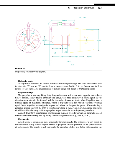
FIGURE 6.11
Magnetically coupled thruster diagram.
Hydraulic motor
The hydraulic version of the thruster motor is a much simpler design. The valve pack directs fluid to either the “A” port or “B” port to drive a motor—pump fluid to A to go forward and to B to reverse (or vice versa). The small nuances of thruster design will be left to OEM salespersons.
Propeller design
The propeller is a turning lifting body designed to move and vector water opposite to the direc- tion of motion. Many thruster propellers are designed so their efficiency is much higher in one direction (most often in the forward and the down directions) than in the other. Propellers have a nominal speed of maximum efficiency, which is hopefully near the vehicle’s normal operating speed. Some propellers are designed for speed and others are designed for power. When selecting a propeller, choose one with the ROV’s operating envelope in mind. The desired operating objectives should be achieved through efficient propeller output below the normal operating envelope.
Also, if diver/ROV simultaneous operations are planned, propeller covers are generally a good idea and are sometime required by diving standards organizations (e.g., IMCA, ADCI).
Kort nozzle
A kort nozzle is common on most underwater thruster models. The efficacy of a kort nozzle is the mechanism’s help in reducing the amount of propeller vortices generated as the propeller turns at high speeds. The nozzle, which surrounds the propeller blades, also helps with reducing the
