
Page 179 - The ROV Manual - A User Guide for Remotely Operated Vehicles 2nd edition
P. 179
168 CHAPTER 8 Cables and Connectors
FIGURE 8.4
(a) Metal body insert with glass seal of pins. (b) Molded epoxy body insert with pins. Note alignment key molded into base of insert.
(Courtesy SeaCon.)
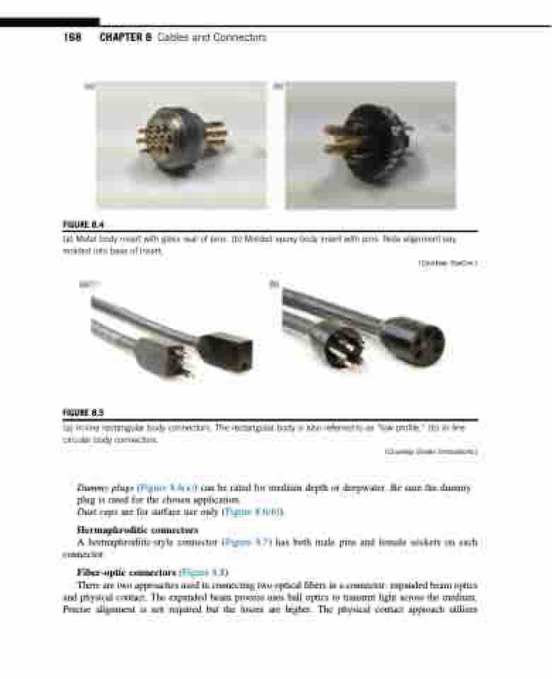
FIGURE 8.5
(a) In-line rectangular body connectors. The rectangular body is also referred to as “low profile.” (b) In-line circular body connectors.
(Courtesy Ocean Innovations.)
Dummy plugs (Figure 8.6(a)) can be rated for medium depth or deepwater. Be sure the dummy plug is rated for the chosen application.
Dust caps are for surface use only (Figure 8.6(b)).
Hermaphroditic connectors
A hermaphroditic-style connector (Figure 8.7) has both male pins and female sockets on each connector.
Fiber-optic connectors (Figure 8.8)
There are two approaches used in connecting two optical fibers in a connector: expanded beam optics and physical contact. The expanded beam process uses ball optics to transmit light across the medium. Precise alignment is not required but the losses are higher. The physical contact approach utilizes
