
Page 200 - The ROV Manual - A User Guide for Remotely Operated Vehicles 2nd edition
P. 200
(a)
IMM
Inductive modem module (inside buoy hull)
Metal eye, clevis; swaged to wire forming seawater ground electrode
IM Instrument
(SBE 37-IM, 37-IMP, 39-IM, 16plus-IM, 16plus-IM V2, 44, UIMM, etc.)
1 turn
100 turns
Inductive cable coupler (ICC)
cable coupler (ICC)
Note: Cores are split
for easy installation
Up to 99 more inductive instruments or slave modem
Metal eye, clevis; swaged to wire forming seawater ground electrode
Anchor
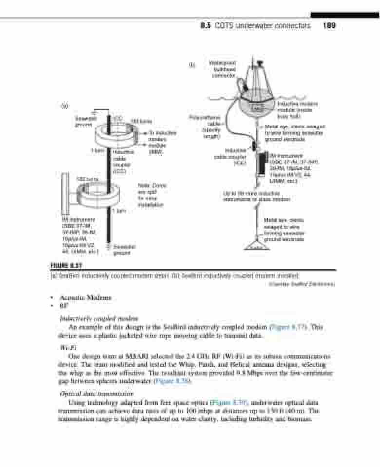
(a) SeaBird inductively coupled modem detail. (b) SeaBird inductively coupled modem installed.
IM instrument (SBE 37-IM, 37-IMP, 39-IM, 16plus-IM, 16plus-IM V2, 44, UIMM, etc.)
FIGURE 8.37
1 turn
Seawater ground
8.5 COTS underwater connectors 189
(b)
Waterproof bulkhead connector
Seawater ICC ground
Polyurethane cable
To inductive (specify modem length)
module
(IMM) Inductive
100 turns
• Acoustic Modems • RF
Inductively coupled modem
An example of this design is the SeaBird inductively coupled modem (Figure 8.37). This device uses a plastic jacketed wire rope mooring cable to transmit data.
Wi-Fi
One design team at MBARI selected the 2.4 GHz RF (Wi-Fi) as its subsea communications device. The team modified and tested the Whip, Patch, and Helical antenna designs, selecting the whip as the most effective. The resultant system provided 9.8 Mbps over the few-centimeter gap between spheres underwater (Figure 8.38).
Optical data transmission
Using technology adapted from free space optics (Figure 8.39), underwater optical data transmission can achieve data rates of up to 100 mbps at distances up to 130 ft (40 m). The transmission range is highly dependent on water clarity, including turbidity and biomass.
(Courtesy SeaBird Electronics.)
