
Page 270 - The ROV Manual - A User Guide for Remotely Operated Vehicles 2nd edition
P. 270
10.2 How it works 259
P n1 v1
θ1
n1 Index v1 Velocity
Normal
O
θ2 Q
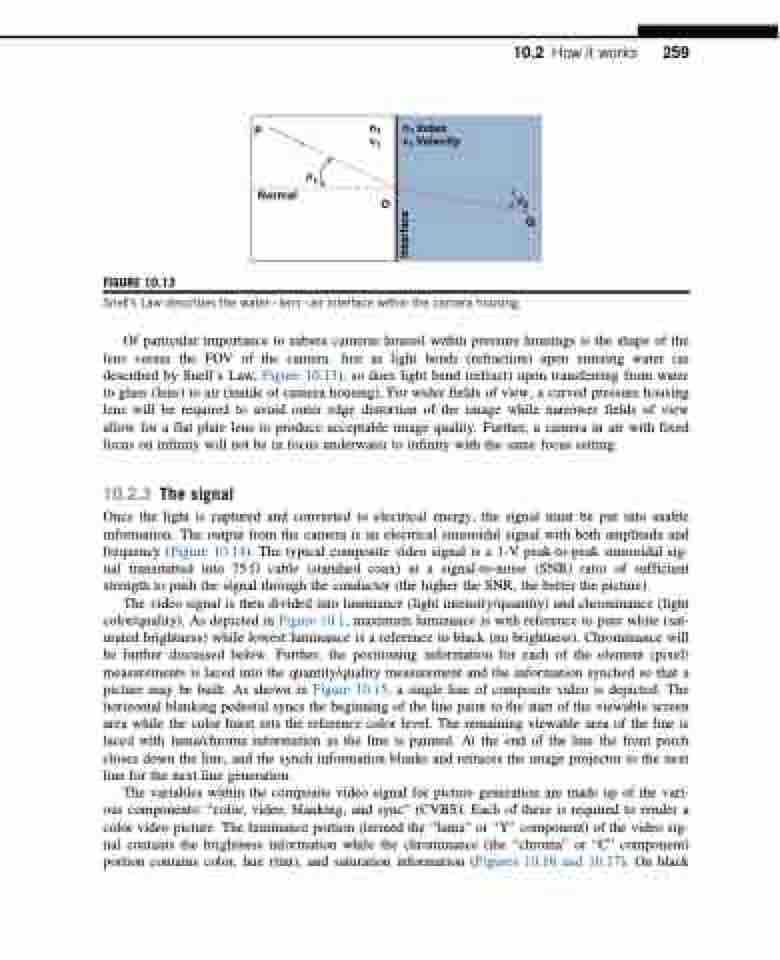
FIGURE 10.13
Snell’s Law describes the waterlensair interface within the camera housing.
Of particular importance to subsea cameras housed within pressure housings is the shape of the lens versus the FOV of the camera. Just as light bends (refraction) upon entering water (as described by Snell’s Law, Figure 10.13), so does light bend (refract) upon transferring from water to glass (lens) to air (inside of camera housing). For wider fields of view, a curved pressure housing lens will be required to avoid outer edge distortion of the image while narrower fields of view allow for a flat plate lens to produce acceptable image quality. Further, a camera in air with fixed focus on infinity will not be in focus underwater to infinity with the same focus setting.
10.2.3 The signal
Once the light is captured and converted to electrical energy, the signal must be put into usable information. The output from the camera is an electrical sinusoidal signal with both amplitude and frequency (Figure 10.14). The typical composite video signal is a 1-V peak-to-peak sinusoidal sig- nal transmitted into 75 Ω cable (standard coax) at a signal-to-noise (SNR) ratio of sufficient strength to push the signal through the conductor (the higher the SNR, the better the picture).
The video signal is then divided into luminance (light intensity/quantity) and chrominance (light color/quality). As depicted in Figure 10.1, maximum luminance is with reference to pure white (sat- urated brightness) while lowest luminance is a reference to black (no brightness). Chrominance will be further discussed below. Further, the positioning information for each of the element (pixel) measurements is laced into the quantity/quality measurement and the information synched so that a picture may be built. As shown in Figure 10.15, a single line of composite video is depicted. The horizontal blanking pedestal syncs the beginning of the line paint to the start of the viewable screen area while the color burst sets the reference color level. The remaining viewable area of the line is laced with luma/chroma information as the line is painted. At the end of the line the front porch closes down the line, and the synch information blanks and retraces the image projector to the next line for the next line generation.
The variables within the composite video signal for picture generation are made up of the vari- ous components: “color, video, blanking, and sync” (CVBS). Each of these is required to render a color video picture. The luminance portion (termed the “luma” or “Y” component) of the video sig- nal contains the brightness information while the chrominance (the “chroma” or “C” component) portion contains color, hue (tint), and saturation information (Figures 10.16 and 10.17). On black
Interface
