
Page 350 - The ROV Manual - A User Guide for Remotely Operated Vehicles 2nd edition
P. 350
342 CHAPTER 13 Communications
(a)
(b)
(c)
T
T
T
FIGURE 13.14
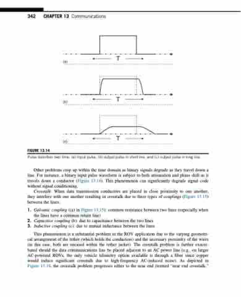
Pulse distortion over time. (a) Input pulse, (b) output pulse in short line, and (c) output pulse in long line.
Other problems crop up within the time domain as binary signals degrade as they travel down a line. For instance, a binary input pulse waveform is subject to both attenuation and phase shift as it travels down a conductor (Figure 13.14). This phenomenon can significantly degrade signal code without signal conditioning.
Crosstalk: When data transmission conductors are placed in close proximity to one another, they interfere with one another resulting in crosstalk due to three types of couplings (Figure 13.15) between the lines:
1. Galvanic coupling ((a) in Figure 13.15): common resistance between two lines (especially when the lines have a common return line)
2. Capacitive coupling (b): due to capacitance between the two lines 3. Inductive coupling (c): due to mutual inductance between the lines
This phenomenon is a substantial problem in the ROV application due to the varying geometri- cal arrangement of the tether (which holds the conductors) and the necessary proximity of the wires (in this case, both are encased within the tether jacket). The crosstalk problem is further exacer- bated should the data communications line be placed adjacent to an AC power line (e.g., on larger AC-powered ROVs, the only vehicle telemetry option available is through a fiber since copper would induce significant crosstalk due to high-frequency AC-induced noise). As depicted in Figure 13.16, the crosstalk problem progresses either to the near end (termed “near end crosstalk,”
