
Page 356 - The ROV Manual - A User Guide for Remotely Operated Vehicles 2nd edition
P. 356
348 CHAPTER 13 Communications
FIGURE 13.21
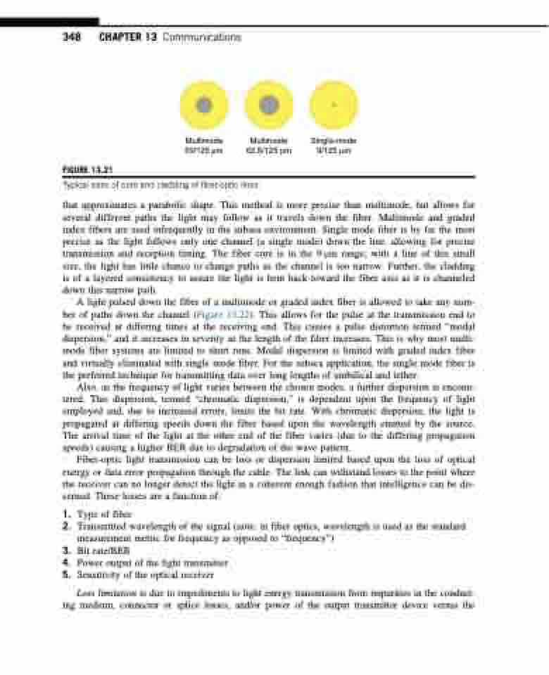
Multimode Multimode Single-mode 50/125 μm 62.5/125 μm 9/125 μm
Typical sizes of core and cladding of fiber-optic lines.
that approximates a parabolic shape. This method is more precise than multimode, but allows for several different paths the light may follow as it travels down the fiber. Multimode and graded index fibers are used infrequently in the subsea environment. Single mode fiber is by far the most precise as the light follows only one channel (a single mode) down the line, allowing for precise transmission and reception timing. The fiber core is in the 9 μm range; with a line of this small size, the light has little chance to change paths as the channel is too narrow. Further, the cladding is of a layered consistency to assure the light is bent back toward the fiber axis as it is channeled down this narrow path.
A light pulsed down the fiber of a multimode or graded index fiber is allowed to take any num- ber of paths down the channel (Figure 13.22). This allows for the pulse at the transmission end to be received at differing times at the receiving end. This causes a pulse distortion termed “modal dispersion,” and it increases in severity as the length of the fiber increases. This is why most multi- mode fiber systems are limited to short runs. Modal dispersion is limited with graded index fiber and virtually eliminated with single mode fiber. For the subsea application, the single mode fiber is the preferred technique for transmitting data over long lengths of umbilical and tether.
Also, as the frequency of light varies between the chosen modes, a further dispersion is encoun- tered. This dispersion, termed “chromatic dispersion,” is dependent upon the frequency of light employed and, due to increased errors, limits the bit rate. With chromatic dispersion, the light is propagated at differing speeds down the fiber based upon the wavelength emitted by the source. The arrival time of the light at the other end of the fiber varies (due to the differing propagation speeds) causing a higher BER due to degradation of the wave pattern.
Fiber-optic light transmission can be loss or dispersion limited based upon the loss of optical energy or data error propagation through the cable. The link can withstand losses to the point where the receiver can no longer detect the light in a coherent enough fashion that intelligence can be dis- cerned. These losses are a function of:
1. Type of fiber
2. Transmitted wavelength of the signal (note: in fiber optics, wavelength is used as the standard
measurement metric for frequency as opposed to “frequency”)
3. Bit rate/BER
4. Power output of the light transmitter
5. Sensitivity of the optical receiver
Loss limitation is due to impediments to light energy transmission from impurities in the conduct-
ing medium, connector or splice losses, and/or power of the output transmitter device versus the
