
Page 406 - The ROV Manual - A User Guide for Remotely Operated Vehicles 2nd edition
P. 406
coming from the zero angle of incidence along with another “bright spot” located in the corners. The corners will not be depicted as square due to the sound multipath as the beam approaches the corner point. Instead of a square corner, the sonar display will depict a rounded corner due to the sound reflection as the beam sweeps the corner.
15.1.11 Sound backscatter
Backscatter is the reflected sound from any object being insonified—the analysis of which is the subject of active sonar systems. Backscatter is analyzed for any number of parameters to solve par- ticular operational needs. Some examples of backscatter analysis follow:
• Multiple bounce depth sounder backscatter is analyzed with acoustic seabed classification systems to determine the texture and makeup of the sea bottom (sand, mud, rock, oyster bed, kelp, etc.) for environmental monitoring as well as vessel navigation.
• Doppler shift backscatter is used for vehicle speed over ground as well as current/wave profiling.
• Frequency shift backscatter is analyzed in CHIRP sonar systems (see Figures 15.2215.24) to discriminate between objects in close proximity.
• Simple high-frequency backscatter can characterize a target as to aspect, texture, surface features, and orientation.
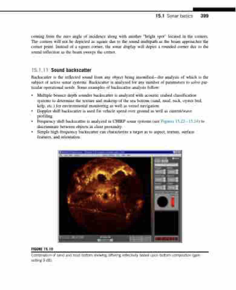
FIGURE 15.10
Combination of sand and mud bottom showing differing reflectivity based upon bottom composition (gain setting 9 dB).
15.1 Sonar basics 399
