
Page 409 - The ROV Manual - A User Guide for Remotely Operated Vehicles 2nd edition
P. 409
402 CHAPTER 15 Sonar
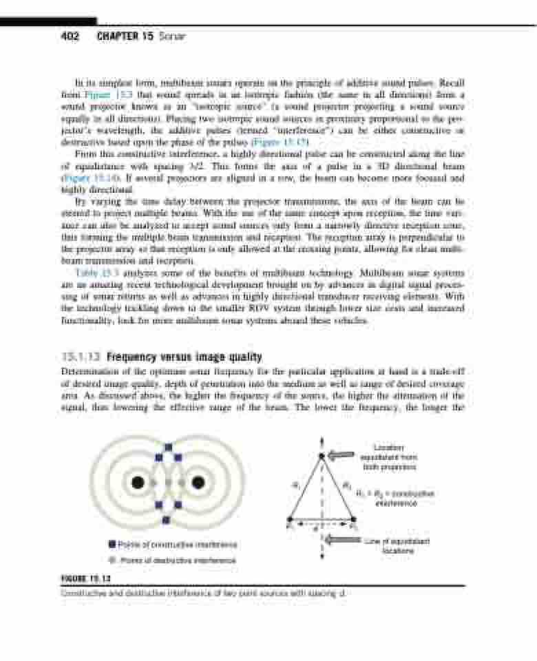
In its simplest form, multibeam sonars operate on the principle of additive sound pulses. Recall from Figure 15.3 that sound spreads in an isotropic fashion (the same in all directions) from a sound projector known as an “isotropic source” (a sound projector projecting a sound source equally in all directions). Placing two isotropic sound sources in proximity proportional to the pro- jector’s wavelength, the additive pulses (termed “interference”) can be either constructive or destructive based upon the phase of the pulses (Figure 15.13).
From this constructive interference, a highly directional pulse can be constructed along the line of equidistance with spacing λ/2. This forms the axis of a pulse in a 3D directional beam (Figure 15.14). If several projectors are aligned in a row, the beam can become more focused and highly directional.
By varying the time delay between the projector transmissions, the axis of the beam can be steered to project multiple beams. With the use of the same concept upon reception, the time vari- ance can also be analyzed to accept sound sources only from a narrowly directive reception cone, thus forming the multiple beam transmission and reception. The reception array is perpendicular to the projector array so that reception is only allowed at the crossing points, allowing for clean multi- beam transmission and reception.
Table 15.3 analyzes some of the benefits of multibeam technology. Multibeam sonar systems are an amazing recent technological development brought on by advances in digital signal proces- sing of sonar returns as well as advances in highly directional transducer receiving elements. With the technology trickling down to the smaller ROV system through lower size costs and increased functionality, look for more multibeam sonar systems aboard these vehicles.
15.1.13 Frequency versus image quality
Determination of the optimum sonar frequency for the particular application at hand is a trade-off of desired image quality, depth of penetration into the medium as well as range of desired coverage area. As discussed above, the higher the frequency of the source, the higher the attenuation of the signal, thus lowering the effective range of the beam. The lower the frequency, the longer the
FIGURE 15.13
R1 R2
Location equidistant from both projectors
R1 = R2 = constructive interference
P1 d P2
Points of constructive interference Points of destructive interference
Line of equidistant locations
Constructive and destructive interference of two point sources with spacing d.
