
Page 444 - The ROV Manual - A User Guide for Remotely Operated Vehicles 2nd edition
P. 444
16.6 Types of positioning technologies 437
(a)
(b) (c)
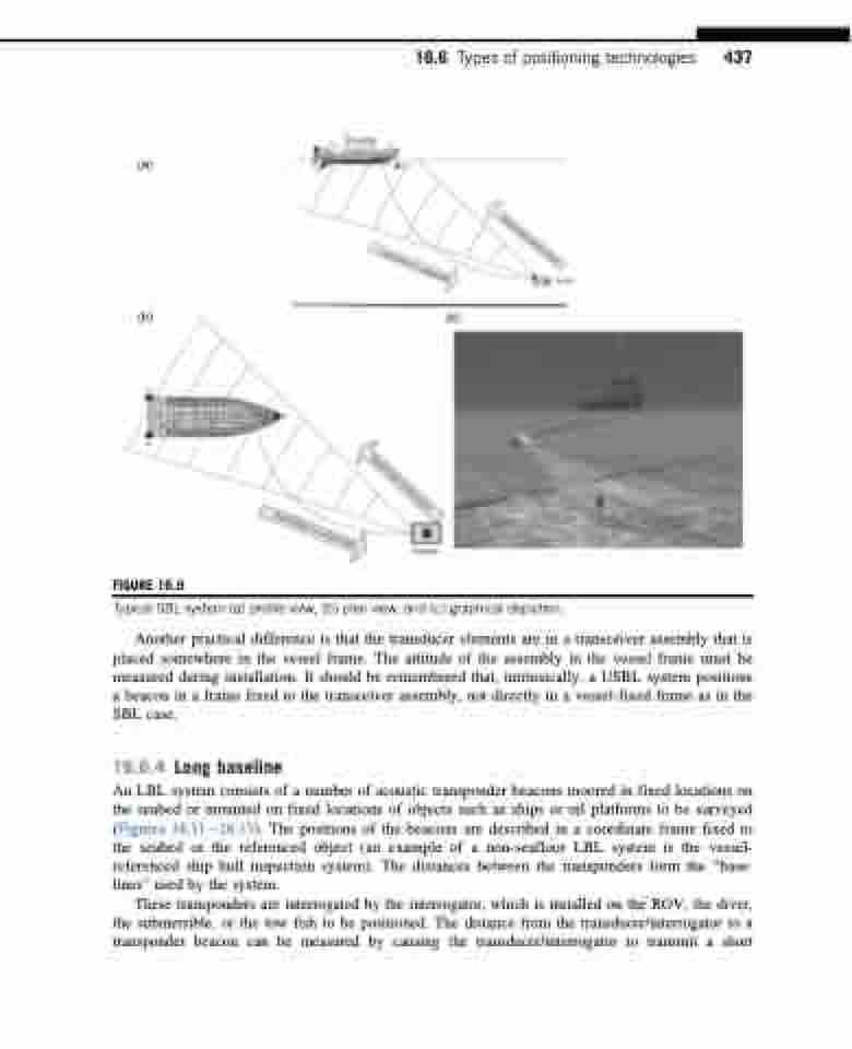
FIGURE 16.9
Typical SBL system (a) profile view, (b) plan view, and (c) graphical depiction.
Another practical difference is that the transducer elements are in a transceiver assembly that is placed somewhere in the vessel frame. The attitude of the assembly in the vessel frame must be measured during installation. It should be remembered that, intrinsically, a USBL system positions a beacon in a frame fixed to the transceiver assembly, not directly in a vessel-fixed frame as in the SBL case.
16.6.4 Long baseline
An LBL system consists of a number of acoustic transponder beacons moored in fixed locations on the seabed or mounted on fixed locations of objects such as ships or oil platforms to be surveyed (Figures 16.1116.13). The positions of the beacons are described in a coordinate frame fixed to the seabed or the referenced object (an example of a non-seafloor LBL system is the vessel- referenced ship hull inspection system). The distances between the transponders form the “base- lines” used by the system.
These transponders are interrogated by the interrogator, which is installed on the ROV, the diver, the submersible, or the tow fish to be positioned. The distance from the transducer/interrogator to a transponder beacon can be measured by causing the transducer/interrogator to transmit a short
