
Page 460 - The ROV Manual - A User Guide for Remotely Operated Vehicles 2nd edition
P. 460
454 CHAPTER 17 Navigational Sensors
17.1 Payload sensors versus vehicle sensors
As explained in Chapter 11, typical commercial ROV systems come equipped with a basic set of sensors for navigating the vehicle under normal conditions. These sensors are typically of a lower sensitivity as the need to position a vehicle in a basic orientation of heading/depth is simple.
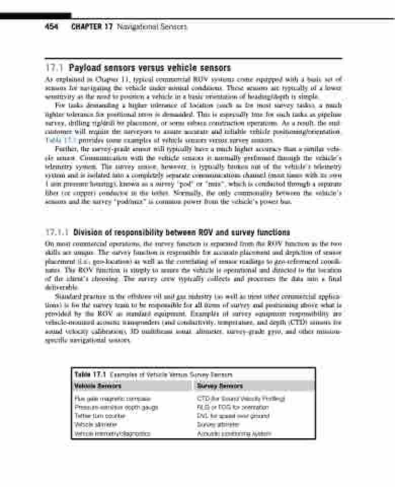
For tasks demanding a higher tolerance of location (such as for most survey tasks), a much tighter tolerance for positional error is demanded. This is especially true for such tasks as pipeline survey, drilling rig/drill bit placement, or some subsea construction operations. As a result, the end- customer will require the surveyors to assure accurate and reliable vehicle positioning/orientation. Table 17.1 provides some examples of vehicle sensors versus survey sensors.
Further, the survey-grade sensor will typically have a much higher accuracy than a similar vehi- cle sensor. Communication with the vehicle sensors is normally performed through the vehicle’s telemetry system. The survey sensor, however, is typically broken out of the vehicle’s telemetry system and is isolated into a completely separate communications channel (most times with its own 1 atm pressure housing), known as a survey “pod” or “mux”, which is conducted through a separate fiber (or copper) conductor in the tether. Normally, the only commonality between the vehicle’s sensors and the survey “pod/mux” is common power from the vehicle’s power bus.
17.1.1 Division of responsibility between ROV and survey functions
On most commercial operations, the survey function is separated from the ROV function as the two skills are unique. The survey function is responsible for accurate placement and depiction of sensor placement (i.e., geo-location) as well as the correlating of sensor readings to geo-referenced coordi- nates. The ROV function is simply to assure the vehicle is operational and directed to the location of the client’s choosing. The survey crew typically collects and processes the data into a final deliverable.
Standard practice in the offshore oil and gas industry (as well as most other commercial applica- tions) is for the survey team to be responsible for all items of survey and positioning above what is provided by the ROV as standard equipment. Examples of survey equipment responsibility are vehicle-mounted acoustic transponders (and conductivity, temperature, and depth (CTD) sensors for sound velocity calibration), 3D multibeam sonar, altimeter, survey-grade gyro, and other mission- specific navigational sensors.
Table 17.1 Examples of Vehicle Versus Survey Sensors
Vehicle Sensors Survey Sensors
Flux gate magnetic compass Pressure-sensitive depth gauge Tether turn counter
Vehicle altimeter
Vehicle telemetry/diagnostics
CTD (for Sound Velocity Profiling) RLG or FOG for orientation
DVL for speed over ground Survey altimeter
Acoustic positioning system
