
Page 472 - The ROV Manual - A User Guide for Remotely Operated Vehicles 2nd edition
P. 472
466
CHAPTER 17 Navigational Sensors
(a)
(b)
FIGURE 17.12
Surge
Roll
Heave
Yaw
Fx
Z
Mx
Fy
X
Y
My
Fz
Mz
Pitch
Sway
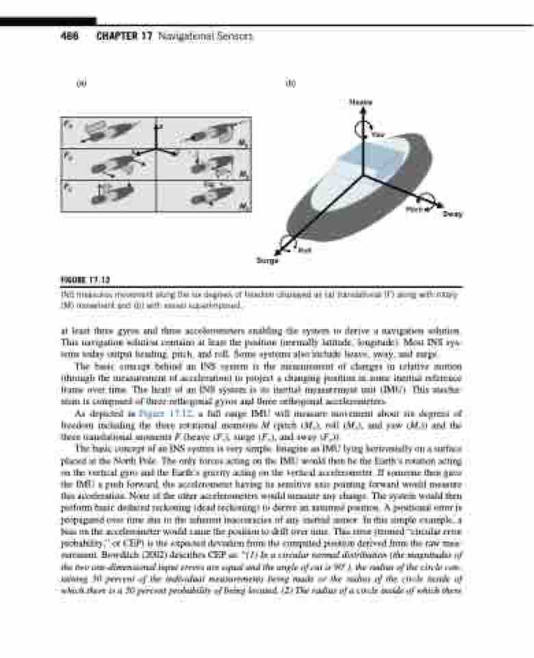
INS measures movement along the six degrees of freedom displayed as (a) translational (F) along with rotary (M) movement and (b) with vessel superimposed.
at least three gyros and three accelerometers enabling the system to derive a navigation solution. This navigation solution contains at least the position (normally latitude, longitude). Most INS sys- tems today output heading, pitch, and roll. Some systems also include heave, sway, and surge.
The basic concept behind an INS system is the measurement of changes in relative motion (through the measurement of acceleration) to project a changing position in some inertial reference frame over time. The heart of an INS system is its inertial measurement unit (IMU). This mecha- nism is composed of three orthogonal gyros and three orthogonal accelerometers.
As depicted in Figure 17.12, a full range IMU will measure movement about six degrees of freedom including the three rotational moments M (pitch (My), roll (Mx), and yaw (Mz)) and the three translational moments F (heave (Fz), surge (Fx), and sway (Fy)).
The basic concept of an INS system is very simple. Imagine an IMU lying horizontally on a surface placed at the North Pole. The only forces acting on the IMU would then be the Earth’s rotation acting on the vertical gyro and the Earth’s gravity acting on the vertical accelerometer. If someone then gave the IMU a push forward, the accelerometer having its sensitive axis pointing forward would measure this acceleration. None of the other accelerometers would measure any change. The system would then perform basic deduced reckoning (dead reckoning) to derive an assumed position. A positional error is propagated over time due to the inherent inaccuracies of any inertial sensor. In this simple example, a bias on the accelerometer would cause the position to drift over time. This error (termed “circular error probability,” or CEP) is the expected deviation from the computed position derived from the raw mea- surement. Bowditch (2002) describes CEP as: “(1) In a circular normal distribution (the magnitudes of the two one-dimensional input errors are equal and the angle of cut is 90), the radius of the circle con- taining 50 percent of the individual measurements being made or the radius of the circle inside of which there is a 50 percent probability of being located. (2) The radius of a circle inside of which there
