
Page 485 - The ROV Manual - A User Guide for Remotely Operated Vehicles 2nd edition
P. 485
480 CHAPTER 18 Ancillary Sensors
Z
X Y
FIGURE 18.3
Magnetic field
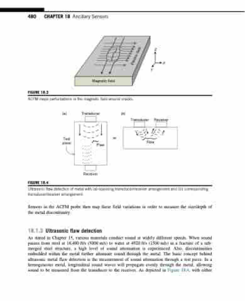
ACFM maps perturbations in the magnetic field around cracks.
(a) Transducer
Test piece
Receiver
Ultrasonic flaw detection of metal with (a) opposing transducer/receiver arrangement and (b) corresponding transducer/receiver arrangement.
Sensors in the ACFM probe then map these field variations in order to measure the size/depth of the metal discontinuity.
18.1.3 Ultrasonic flaw detection
As stated in Chapter 15, various materials conduct sound at widely different speeds. When sound passes from steel at 16,400 ft/s (5000 m/s) to water at 4920 ft/s (1500 m/s) in a fracture of a sub- merged steel structure, a high level of sound attenuation is experienced. Also, discontinuities embedded within the metal further attenuate sound through the metal. The basic concept behind ultrasonic metal flaw detection is the measurement of sound attenuation through a test piece. In a homogeneous metal, longitudinal sound waves will propagate evenly through the metal, allowing sound to be measured from the transducer to the receiver. As depicted in Figure 18.4, with either
FIGURE 18.4
Flaw
or
(b)
Transducer
Receiver
Flaw
Electric field
