
Page 609 - The ROV Manual - A User Guide for Remotely Operated Vehicles 2nd edition
P. 609
22.1 Standard operating procedures 609
manipulator and/or hydraulic circuit in case a stuck control valve or control circuit is energized,
thus moving the manipulator in an uncontrolled fashion.
• Test the lights, camera/manipulator/tooling functions, and thrusters. Check that adequate video
is obtained and that any video recording equipment is working properly. In most cases, underwater lights are not designed for operation out of water for any length of time. After testing the function of the lights, quickly turn the lights off to prevent excessive heat buildup. (At a recent trade show booth in Paris, a sound like a gunshot made all nearby duck for cover— it was an incandescent underwater light at a nearby booth that overheated and exploded.)
• After placing the vehicle in the water, check the vehicle for ballast and trim.
22.1.5 Specific consideration for operational deployment of ROVs
22.1.5.1 General considerations
In this section, the primary focus will be on the OCROV system. As discussed in Chapter 3, there are varying levels of capability with differing sizes of OCROV systems. In the following sections, a series of operational tasks will be listed. The listing will be accompanied with suggested methods of how to approach each task, based upon the operating characteristics of different size classifica- tions of OCROV systems.
The classification of each ROV system (small, medium, and large) is based upon the systems evaluated during OCROV procedures testing. Each is capable of performing general tasks (i.e., ship hull inspection, pier and mooring inspections, etc.) under ideal conditions. The more difficult the conditions become (e.g., higher currents, longer stand-off from work site, and higher tether drag), the less likely the system will be able to pull its tether to the work site.
22.1.5.2 Performance considerations
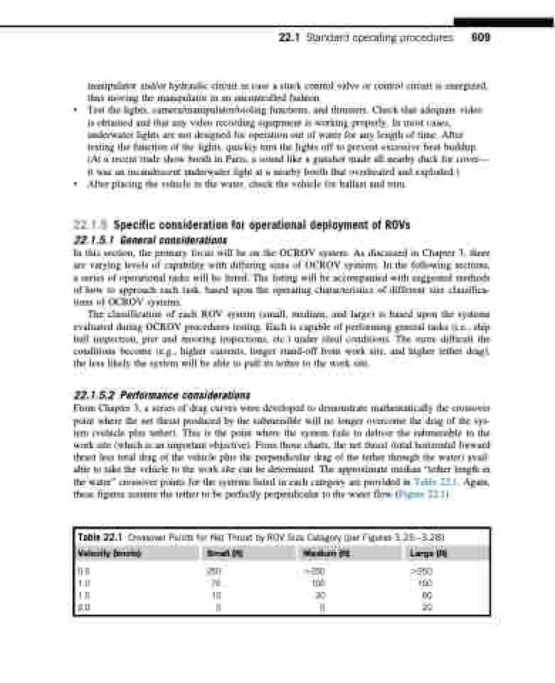
From Chapter 3, a series of drag curves were developed to demonstrate mathematically the crossover point where the net thrust produced by the submersible will no longer overcome the drag of the sys- tem (vehicle plus tether). This is the point where the system fails to deliver the submersible to the work site (which is an important objective). From those charts, the net thrust (total horizontal forward thrust less total drag of the vehicle plus the perpendicular drag of the tether through the water) avail- able to take the vehicle to the work site can be determined. The approximate median “tether length in the water” crossover points for the systems listed in each category are provided in Table 22.1. Again, these figures assume the tether to be perfectly perpendicular to the water flow (Figure 22.1).
Table 22.1 Crossover Points for Net Thrust by ROV Size Category (per Figures 3.253.28)
Velocity (knots) Small (ft) Medium (ft) Large (ft)
0.5 250 .250 .250 1.0 75 100 150 1.5 10 30 60 2.0 0 0 20
