Page 645 - The ROV Manual - A User Guide for Remotely Operated Vehicles 2nd edition
P. 645
  646 CHAPTER 23 The Future of ROV Technology
 23.2 Fiber-optic linked ROVs
One of the previously mentioned drawbacks to an ROV is the limitations imposed by the umbilical/ tether. Yes, it provides the power and communication link necessary for the ROV to operate, but (like a leash on a dog) it constrains where it can go. And, in some (read, “Most”) environments, it can become entangled—possibly causing the loss of the vehicle. One approach would be to change from a bulky and costly integrated power/telemetry cable to an inexpensive expendable (or reus- able) copper-less fiber-optic tether.
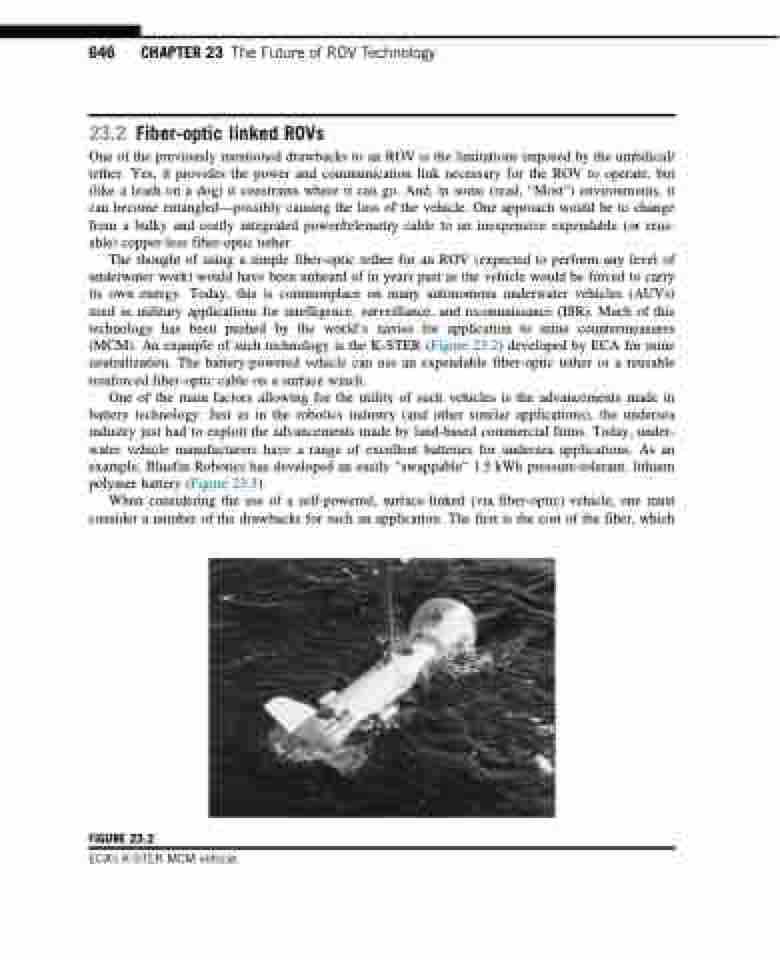
The thought of using a simple fiber-optic tether for an ROV (expected to perform any level of underwater work) would have been unheard of in years past as the vehicle would be forced to carry its own energy. Today, this is commonplace on many autonomous underwater vehicles (AUVs) used in military applications for intelligence, surveillance, and reconnaissance (ISR). Much of this technology has been pushed by the world’s navies for application to mine countermeasures (MCM). An example of such technology is the K-STER (Figure 23.2) developed by ECA for mine neutralization. The battery-powered vehicle can use an expendable fiber-optic tether or a reusable reinforced fiber-optic cable on a surface winch.
One of the main factors allowing for the utility of such vehicles is the advancements made in battery technology. Just as in the robotics industry (and other similar applications), the undersea industry just had to exploit the advancements made by land-based commercial firms. Today, under- water vehicle manufacturers have a range of excellent batteries for undersea applications. As an example, Bluefin Robotics has developed an easily “swappable” 1.5 kWh pressure-tolerant, lithium polymer battery (Figure 23.3).
When considering the use of a self-powered, surface-linked (via fiber-optic) vehicle, one must consider a number of the drawbacks for such an application. The first is the cost of the fiber, which
FIGURE 23.2
ECA’s K-STER MCM vehicle.


