Page 13 - Destaco - Precision Parallel Grippers
P. 13

2p options & Accessories


      2-Jaw Parallel Grippers | Dimensions and Technical Specifications


       Option (V): Viton® Seals
       Gripper with Viton® seals allows for use in high temperature environments  [-30 ° C or 150 ° C].


       Accessory (E): Protective Boot
       The accessory (E) is a protective boot that fits over the gripper. It protects the mechanism and thus improves the
       life of the gripper in hostile environments. The accessory (E) causes a different location of the fingers on the jaws
       as compared to the standard installation. Before attaching the boot, perform the following steps:
        1. Mount gripper to machine.
        2. Slip boot over gripper and secure in place.
        3. Attached fingers to jaws using finger adapter.

       Depending on the environment 2 types of envelopes are available:
        (E) Envelope of black or brown PVC for environmental grinding with emery presence.
        (E3) red envelope containing KEVLAR fireproof silicone environment for hot chips and weld spatter.
       The accessory (E) is incompatible with the accessory (SD)


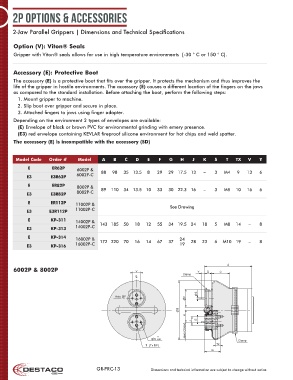
        Model Code    Order #     Model     A   B    C    D    E   F    G   H    J    K    S   T   TX    V   Y
             E         ER62P     6002P &    88  98   35 13.5   8   29  29 17.5 13     –    3   M4   9   13   6
            E3        E3R62P     6002P-C

             E         ER82P     8002P &
            E3        E3R82P     8002P-C   89  110   34 13.5 10    33  30 22.3 16     –    3   M5   10  16   6
             E        ER112P     11002P &
            E3        E3R112P    11002P-C                               See Drawing

             E        KP-311     14002P &
            E3        KP-313     14002P-C  143 185   50  18   12   55  34 19.5 24    18    5   M8   14   –   8
             E        KP-314     16002P &                                   24
            E3        KP-316     16002P-C  172 220   70  16   14   67  37   19   28  23    6  M10 19     –   8


                                                                                                A
       6002P & 8002P                                      V                         Y   D    C
                                                                             Clamp
                                                          C L


                                                                                   S
                                                 Axis ØF                      F

                                                                            B
                                                                              H
                                                                                   E
                                                                                 J
                                                                              Jaws Closed
                                                                   0
                                                                 S -0,01                             Clamp
                                                              T (Tx DP)                    Tx
                                                                                         G


                                         GR-PRC-13              Dimensions and technical information are subject to change without notice
   8   9   10   11   12   13   14   15   16   17   18