
Page 324 - Icon Ridge Presents ORION
P. 324
Turning tools \ Technical introduction - knurling
Technical information, knurl pressing
in knurl pressing, the material is subject to chipless deformation. The material is cold-formed via the knurling wheel and fl ows outwards. This forming process
increases the diameter of the workpiece. The following list provides an overview of bulging for the various pitches and materials.
the most suitable knurling materials are:
All ferrous materials with a stability of max. 1700 N/mm2 and an elongation of at least 4 - 5%
Non-ferrous base metals
Hardwood
Plastic corresponding to the requirements of the elongation and tensile strength
An increase in diameter is a particular characteristic of knurl forming. A diameter increase of approx. 40% of the used knurling pitch is considered an empirical value
for larger initial diameters. the initial diameter can be calculated according to the following formula:
d2 = Starting diameter (rotation diameter) [mm]
d1 = End diameter [mm]
d 2 = d 1 – (X · t) X = The value X can be derived from the following table
t = Pitch
Knurl form Value X
Parallel to axis, form AA 0.50
Left knurl, form BL 0.50
Right knurl, form BR 0.50
Cross knurl, tips raised, form KE 0.67
Cross knurl, tips recessed, form KV 0.33
Left/right knurl, tips raised, form GE 0.67
Left/right knurl, tips recessed, form GV 0.33
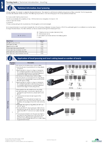
Application of knurl pressing and knurl cutting based on number of knurls
Knurling Description
wheels
For recess knurls with various recess profi les
Axial knurls are only possible with knurling wheels
of form AA RAA 1xBR 1xBL RGE30° 1xGV45° 1xGE30° RGV45° 1xKV * 1xKE *
RKE
RGV30°
RBL
RBR
RGE45°
RKV
1xAA
1xGV30°
1xGE45°
1 Knurling tools for recess knurling are clamped at
90° and knurling tools for axial knurling at 88° to
the workpiece (prevention of material congestion
Knurl pressing For recess knurls with various recess profi les
towards front edge of the knurling wheel)
Axial knurls are only possible with knurling wheels
of form AA (knurling parallel to axis) and forms BL +
RGE30°
RGE45°
RBR
RBL
BR (left/right knurling)
1xBL30°
2xAA
1xBR45°
2 Knurling tools for recess knurling are clamped at RAA 2xBR 2xBL 1xBR30° 1xBL45°
90° and knurling tools for axial knurling at 88° to
the workpiece (prevention of material congestion
towards front edge of the knurling wheel)
Exclusively for knurls parallel to the axis (RAA)
For left-hand tools, a knurl cutter roller BL 30° is
used and for right-hand tools, a knurl cutter roller
BR 30°
1 Tools must be clamped at right angles to the
workpiece RAA RBR 15° RBL 15°
1x15° R
Marking points for the precise tip height are 1x30° (R/L) RBR 30° 1x15° L
RBR 30°
indicated on the side of the head; for tools for CNC 1x90° 1x90°
Knurl cutting Facilitates left/right knurling (RGE) with 30° and
machines, the top edge of the shaft is the reference
edge
with 45° spiral
For knurls RGE 30°, two knurl cutter rollers AA are
inserted into the tool; for RGE 45° knurls, one knurl
cutter wheel BR 15° and one knurl cutter wheel BL
2 15°
The workpiece diameter and the exact tip height is RGE 45° RGE 30°
1x15° R
2x90°
set using the adjustment scale. Prior to the actual 1x15° L
milling process, guide the tool against the work-
piece and check whether the two knurl cutter rollers
engage simultaneously
Source: Hahn+Kolb Werkzeuge GmbH
Technical data subject to change. www.iconridge.com
Availability subject to country specific rules and regulations. 324
0696_EN_2018_KERN[21848050]-n.indd 696 12/17/2018 3:33:48 PM