
Page 279 - Industrial Tools Catalog (2)
P. 279
Force measurement and weighing technology \ Cylindrical spring balances and dynamometers
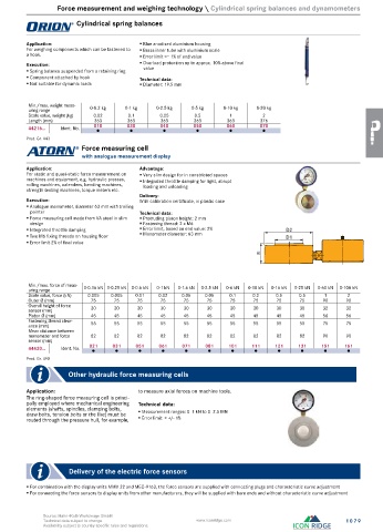
Cylindrical spring balances
Application: Blue anodised aluminium housing
For weighing components which can be fastened to Brass inner tube with aluminium scale
a hook. Error limit <= 1% of end value
Execution: Overload protection up to approx. 10% above final
value
Spring balance suspended from a retaining ring
Component attached by hook Technical data:
Not suitable for dynamic loads Diameter: 19.5 mm
Min./max. weight meas-
uring range 0-0.2 kg 0-1 kg 0-2.5 kg 0-5 kg 0-10 kg 0-20 kg
Scale value, weight (kg) 0.02 0.1 0.25 0.5 1 2
Length (mm) 363 363 363 363 363 376
44216... Ident. No. 010 030 040 050 060 070
●
●
●
●
●
●
Prod. Gr. 443
Force measuring cell
with analogue measurement display
Application: Advantage:
For static and quasi-static force measurement on Very slim design for in constricted spaces
machines and equipment, e.g. hydraulic presses, Integrated throttle damping for light, abrupt
rolling machines, calenders, bending machines, loading and unloading
strength testing machines, torque meters etc.
Delivery:
Execution: With calibration certificate, in plastic case
Analogue manometer, diameter 63 mm with trailing
pointer Technical data:
Force measuring cell made from VA steel in slim Protruding piston height: 2 mm
design Fastening thread: 2 x M6
Integrated throttle damping Error limit, based on end value: 2% D2
Two M6 fixing threads on housing floor Manometer diameter: 63 mm D1
Error limit 2% of final value
H
Min./max. force of meas-
uring range 0-0.16 kN 0-0.25 kN 0-0.6 kN 0-1 kN 0-1.6 kN 0-2.5 kN 0-6 kN 0-10 kN 0-16 kN 0-25 kN 0-60 kN 0-100 kN
Scale value, force (kN) 0.005 0.005 0.01 0.02 0.05 0.05 0.1 0.2 0.5 0.5 1 2
Outer Ø (mm) 75 75 75 75 75 75 75 75 75 75 90 90
Overall height of force 30 30 30 30 30 30 30 30 30 30 32 32
sensor (mm)
Piston Ø (mm) 45 45 45 45 45 45 45 45 45 45 56 56
Fastening thread clear- 55 55 55 55 55 55 55 55 55 55 75 75
ance (mm)
Mean distance between
manometer and force 82 82 82 82 82 82 82 82 82 82 90 90
sensor (mm)
44420... Ident. No. 021 031 051 061 071 081 101 111 121 131 151 161
●
●
●
●
●
●
●
●
●
●
●
●
Prod. Gr. 490
Other hydraulic force measuring cells
Application: to measure axial forces on machine tools.
The ring-shaped force measuring cell is princi-
pally employed where mechanical engineering Technical data:
elements (shafts, spindles, clamping bolts,
draw bolts, tension bolts or the like) must be Measurement ranges: 0–1 kN to 0–2.5 MN
routed through the pressure hull, for example, Error limit: < +/- 1%
Delivery of the electric force sensors
For combination with the display units MMV 22 and MEC-9163, the force sensors are supplied with connecting plugs and characteristic curve adjustment
For connecting the force sensors to display units from other manufacturers, they will be supplied with bare ends and without characteristic curve adjustment
Source: Hahn+Kolb Werkzeuge GmbH
Technical data subject to change. www.iconridge.com 1079
Availability subject to country specific rules and regulations.