
Page 122 - Zero Net Energy Case Study Buildings-Volume 1
P. 122
CASE STUDY NO. 6
CLASSROOM & OFFICE BUILDING
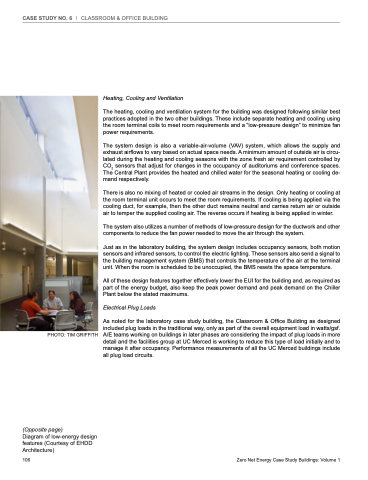
PHOTO: TIM GRIFFITH
Heating, Cooling and Ventilation
The heating, cooling and ventilation system for the building was designed following similar best practices adopted in the two other buildings. These include separate heating and cooling using the room terminal coils to meet room requirements and a “low-pressure design” to minimize fan power requirements.
The system design is also a variable-air-volume (VAV) system, which allows the supply and exhaust airflows to vary based on actual space needs. A minimum amount of outside air is circu- lated during the heating and cooling seasons with the zone fresh air requirement controlled by CO2 sensors that adjust for changes in the occupancy of auditoriums and conference spaces. The Central Plant provides the heated and chilled water for the seasonal heating or cooling de- mand respectively.
There is also no mixing of heated or cooled air streams in the design. Only heating or cooling at the room terminal unit occurs to meet the room requirements. If cooling is being applied via the cooling duct, for example, then the other duct remains neutral and carries return air or outside air to temper the supplied cooling air. The reverse occurs if heating is being applied in winter.
The system also utilizes a number of methods of low-pressure design for the ductwork and other components to reduce the fan power needed to move the air through the system.
Just as in the laboratory building, the system design includes occupancy sensors, both motion sensors and infrared sensors, to control the electric lighting. These sensors also send a signal to the building management system (BMS) that controls the temperature of the air at the terminal unit. When the room is scheduled to be unoccupied, the BMS resets the space temperature.
All of these design features together effectively lower the EUI for the building and, as required as part of the energy budget, also keep the peak power demand and peak demand on the Chiller Plant below the stated maximums.
Electrical Plug Loads
As noted for the laboratory case study building, the Classroom & Office Building as designed included plug loads in the traditional way, only as part of the overall equipment load in watts/gsf. A/E teams working on buildings in later phases are considering the impact of plug loads in more detail and the facilities group at UC Merced is working to reduce this type of load initially and to manage it after occupancy. Performance measurements of all the UC Merced buildings include all plug load circuits.
(Opposite page)
Diagram of low-energy design features (Courtesy of EHDD Architecture)
106
Zero Net Energy Case Study Buildings: Volume 1
