
Page 161 - 2022FittingsCatalog
P. 161
TECHNICAL INFORMATION
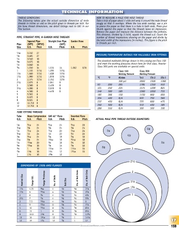
THREAD DIMENSIONS HOW TO MEASURE A MALE FIRE HOSE THREAD
The following tables give the actual outside dimension of male Take a strip of paper about 1 wide and wrap it around the male thread
threads in inches as well as the pitch given in threads per inch. For snugly so that it overlaps. Where the two ends overlap, use a pin
fire hose thread dimensions, see detail listings next to G81 in our to pierce the paper so that there is a hole in both ends. Press your
Fire Section. thumb against the paper so that the threads leave an impression.
Remove the paper and measure the distance between the pinholes.
This distance, divided by 3.1416, equals the thread o.d. Count the
PIPE, STRAIGHT PIPE, & GARDEN HOSE THREADS number of thread impressions showing on the paper and divide by
Tapered Pipe Straight Iron Pipe Garden Hose the total width of the impressions (in inches). This figure is the pitch
Pipe (NPT) (NPSH) (GHT) in threads per inch.
Size O.D. Pitch O.D. Pitch O.D. Pitch
1 ⁄16 0.312 27
1 ⁄8 0.405 27 PRESSURE/TEMPERATURE RATINGS FOR MALLEABLE IRON FITTINGS
1 ⁄4 0.540 18
3 ⁄8 0.675 18 The standard malleable fittings shown in this catalog are Class 150
1 ⁄2 0.840 14 and meet the working pressures shown here for that class. Heavier
Class 300 parts are available on special order.
3 ⁄4 1.050 14 1.035 14 1.062 11 1 ⁄2
1 1.315 11 1 ⁄2 1.295 11 1 ⁄2 Class 150 Class 300
1 1 ⁄4 1.660 11 1 ⁄2 1.639 11 1 ⁄2 Working Pressure Working Pressure
1 1 ⁄2 1.900 11 1 ⁄2 1.878 11 1 ⁄2 °C °F All sizes 1 /4- 1 1 /4 - 2 2 /2 - 3
1
1
2 2.375 11 1 ⁄2 2.352 11 1 ⁄2
2 1 ⁄2 2.875 8 2.841 8 300 psi 2000 1500 1000
3 3.500 8 3.470 8 93 200 265 1785 1350 910
3 1 ⁄2 4.000 8 3.970 8 121 250 225 1575 1200 825
4 4.500 8 4.470 8 149 300 185 1360 1050 735
5 5.563 8 185 366 150 1150 900 650
6 6.625 8 204 400 N/A 935 750 560
8 8.625 8 232 450 N/A 725 600 475
10 10.750 8
12 12.750 8 260 500 N/A 510 450 385
288 550 N/A 300 300 300
TUBE FITTING THREADS
Tube Brass Compression SAE 45° Flare Inverted Flare
O.D. O.D. Pitch O.D. Pitch O.D. Pitch ACTUAL MALE PIPE THREAD OUTSIDE DIAMETERS:
1 ⁄8 5 ⁄16 24 5 ⁄16 24 5 ⁄16 28
3 ⁄16 3 ⁄8 24 3 ⁄8 24 3 ⁄8 24 1 ⁄8
1 ⁄4 7 ⁄16 24 7 ⁄16 20 7 ⁄16 24 1 ⁄4
5 ⁄16 1 ⁄2 24 1 ⁄2 20 1 ⁄2 20
3 ⁄8 9 ⁄16 24 5 ⁄8 18 5 ⁄8 18 1 ⁄2
7 ⁄16 5 ⁄8 24 11 ⁄16 16 11 ⁄16 18
1 ⁄2 11 ⁄16 20 3 ⁄4 16 3 ⁄4 18 3 ⁄4
5 ⁄8 13 ⁄16 18 7 ⁄8 14 7 ⁄8 18
3 ⁄4 1 18 1 1 ⁄16 14 1 1 ⁄16 16 3 ⁄8 3
7 ⁄8 1 1 ⁄8 18 1 1 ⁄4 12 1 3 ⁄16 16
1 1 1 ⁄4 16 1 3 ⁄8 12
1
2 ⁄2
DIMENSIONS OF 150lb ANSI FLANGES 2
Nominal Size Flange O.D. Flange Thickness No. of Bolts Bolt Size Dia. of Bolt Holes Dia. of Bolt Circle 1 ⁄2
1
1
1 ⁄4
1 1 ⁄4 4.25 9 ⁄16 4 1 ⁄2 5 ⁄8 3 1 ⁄8
1 1 ⁄2 5 11 ⁄16 4 1 ⁄2 5 ⁄8 3 7 ⁄8
2 6 3 ⁄4 4 5 ⁄8 3 ⁄4 4 3 ⁄4 1
2 1 ⁄2 7 7 ⁄8 4 5 ⁄8 3 ⁄4 5 3 ⁄4
3 7.5 15 ⁄16 4 5 ⁄8 3 ⁄4 6
4 9 15 ⁄16 8 5 ⁄8 3 ⁄4 7 1 ⁄2
5 10 15 ⁄16 8 3 ⁄4 7 ⁄8 8 1 ⁄2
6 11 1 8 3 ⁄4 7 ⁄8 9 1 ⁄2
8 13.5 1 1 ⁄8 8 3 ⁄4 7 ⁄8 11 3 ⁄4
10 16 1 3 ⁄16 12 7 ⁄8 1 14 1 ⁄4
12 19 1 1 ⁄4 12 7 ⁄8 1 17 17
159