
Page 1172 - Master Catalog 2017, Inch
P. 1172
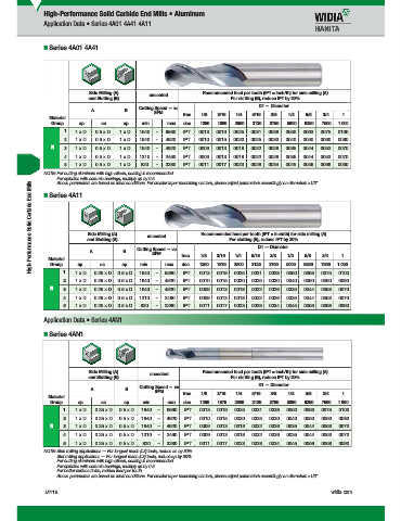
High-Performance Solid Carbide End Mills • Aluminum
Application Data • Series 4A01 4A41 4A11
Series 4A01 4A41
Side Milling (A) Recommended feed per tooth (IPT = inch/th) for side milling (A).
and Slotting (B) uncoated For slotting (B), reduce IPT by 20%.
Cutting Speed — vc D1 — Diameter
A B
SFM frac. 1/8 3/16 1/4 5/16 3/8 1/2 5/8 3/4 1
Material
Group ap ae ap min max dec. .1250 .1880 .2500 .3130 .3750 .5000 .6250 .7500 1.000
1 1 x D 0.5 x D 1 x D 1640 – 6560 IPT .0013 .0019 .0025 .0031 .0038 .0050 .0063 .0075 .0100
2 1 x D 0.5 x D 1 x D 1640 – 4920 IPT .0010 .0015 .0020 .0025 .0030 .0040 .0050 .0060 .0080
N 3 1 x D 0.5 x D 1 x D 1640 – 4920 IPT .0009 .0013 .0018 .0022 .0026 .0035 .0044 .0053 .0070
4 1 x D 0.5 x D 1 x D 1310 – 2460 IPT .0009 .0013 .0018 .0022 .0026 .0035 .0044 .0053 .0070
5 1 x D 0.5 x D 1 x D 820 – 3280 IPT .0011 .0017 .0023 .0028 .0034 .0045 .0056 .0068 .0090
NOTE: For cutting aluminum with high silicon, coating is recommended.
For spindles with ceramic bearings, multiply ap by 0.5.
High-Performance Solid Carbide End Mills and Slotting (B) B Cutting Speed — vc Recommended feed per tooth (IPT = inch/th) for side milling (A).
Above parameters are based on ideal conditions. For smaller taper machining centers, please adjust parameters accordingly on diameters >1/2".
Series 4A11
Side Milling (A)
uncoated
For slotting (B), reduce IPT by 20%.
D1 — Diameter
A
3/8
5/16
1/8
3/16
1/4
1/2
5/8
3/4
1
Material
.1250
.2500
.7500
Group
ae
1.000
.1875
max
ap
dec.
min
.6250
ap
.5000
.3125
.3750
IPT
–
.0040
.0030
.0015
IPT
.0010
2 1 1 x D 0.25 x D 0.5 x D 1640 SFM 6560 frac. .0013 .0019 .0025 .0031 .0038 .0050 .0063 .0075 .0100
–
4920
0.25 x D
.0050
.0060
.0025
1 x D
0.5 x D
1640
.0080
.0020
N 3 1 x D 0.25 x D 0.5 x D 1640 – 4920 IPT .0009 .0013 .0018 .0022 .0026 .0035 .0044 .0053 .0070
4 1 x D 0.25 x D 0.5 x D 1310 – 2460 IPT .0009 .0013 .0018 .0022 .0026 .0035 .0044 .0053 .0070
5 1 x D 0.25 x D 0.5 x D 820 – 3280 IPT .0011 .0017 .0023 .0028 .0034 .0045 .0056 .0068 .0090
Application Data • Series 4AN1
Series 4AN1
Side Milling (A) uncoated Recommended feed per tooth (IPT = inch/th) for side milling (A).
and Slotting (B) For slotting (B), reduce IPT by 20%.
D1 — Diameter
Cutting Speed — vc
A B
SFM frac. 1/8 3/16 1/4 5/16 3/8 1/2 5/8 3/4 1
Material
Group ap ae ap min max dec. .1250 .1875 .2500 .3125 .3750 .5000 .6250 .7500 1.000
1 1 x D 0.25 x D 0.5 x D 1640 – 6560 IPT .0013 .0019 .0025 .0031 .0038 .0050 .0063 .0075 .0100
2 1 x D 0.25 x D 0.5 x D 1640 – 4920 IPT .0010 .0015 .0020 .0025 .0030 .0040 .0050 .0060 .0080
N 3 1 x D 0.25 x D 0.5 x D 1640 – 4920 IPT .0009 .0013 .0018 .0022 .0026 .0035 .0044 .0053 .0070
4 1 x D 0.25 x D 0.5 x D 1310 – 2460 IPT .0009 .0013 .0018 .0022 .0026 .0035 .0044 .0053 .0070
5 1 x D 0.25 x D 0.5 x D 820 – 3280 IPT .0011 .0017 .0023 .0028 .0034 .0045 .0056 .0068 .0090
NOTE: Side milling applications — For longest reach (L3) tools, reduce ae by 30%.
Slot milling applications — For longest reach (L3) tools, reduce ap by 30%.
For cutting aluminum with high silicon, coating is recommended.
For spindles with ceramic bearings, multiply ap by 0.5.
For better surface fi nish, reduce feed per tooth.
Above parameters are based on ideal conditions. For smaller taper machining centers, please adjust parameters accordingly on diameters >1/2".
M116 widia.com
V
Hi hP f
M116 M117 Mi h REBRANDN
16 S lidE dMilli
i
WID M
L WID_Master16_SolidEndMilling_HighPerformance_M116_M117_Minch_REBRAND.indd 116 b 9 20159 14AM 11/11/15 9:39 AM