
Page 1241 - Master Catalog 2017, Inch
P. 1241
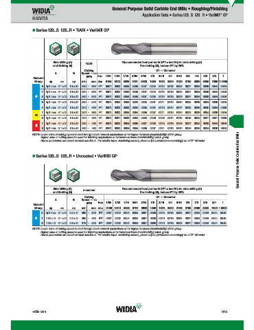
General Purpose Solid Carbide End Mills • Roughing/Finishing
™
Application Data • Series I2B..S I2B..R • VariMill GP
Series I2B..S I2B..R • TiAlN • VariMill GP
Side Milling (A) Recommended feed per tooth (IPT = inch/th) for side milling (A).
and Slotting (B) TiAlN For slotting (B), reduce IPT by 20%.
Cutting D1 — Diameter
A B Speed — vc
SFM frac. 1/64 1/32 1/16 5/64 3/32 1/8 3/16 1/4 5/16 3/8 1/2 5/8 3/4 1
Material
Group ap ae ap min max dec. .0156 .0313 .0625 .0781 .0938 .1250 .1875 .2500 .3125 .3750 .5000 .6250 .7500 1.0000
0 Ap1 max 0.1 x D 0.5 x D 490 – 660 IPT .0001 .0002 .0004 .0005 .0007 .0009 .0013 .0018 .0023 .0027 .0034 .0039 .0044 .0049
1 Ap1 max 0.1 x D 0.5 x D 490 – 660 IPT .0001 .0002 .0004 .0005 .0007 .0009 .0013 .0018 .0023 .0027 .0034 .0039 .0044 .0049
P 2 Ap1 max 0.1 x D 0.5 x D 460 – 620 IPT .0001 .0002 .0004 .0005 .0007 .0009 .0013 .0018 .0023 .0027 .0034 .0039 .0044 .0049
3 Ap1 max 0.1 x D 0.5 x D 390 – 520 IPT .0001 .0002 .0004 .0004 .0005 .0007 .0011 .0015 .0020 .0023 .0029 .0034 .0039 .0045
4 Ap1 max 0.1 x D 0.5 x D 300 – 490 IPT .0001 .0002 .0003 .0004 .0005 .0007 .0010 .0014 .0017 .0020 .0026 .0030 .0034 .0039
1 Ap1 max 0.1 x D 0.5 x D 300 – 380 IPT .0001 .0002 .0004 .0004 .0005 .0007 .0011 .0015 .0020 .0023 .0029 .0034 .0039 .0045
M
2 Ap1 max 0.1 x D 0.5 x D 200 – 260 IPT .0001 .0001 .0003 .0004 .0004 .0006 .0009 .0012 .0016 .0018 .0023 .0027 .0031 .0036
1 Ap1 max 0.1 x D 0.5 x D 390 – 490 IPT .0001 .0002 .0004 .0005 .0007 .0009 .0013 .0018 .0023 .0027 .0034 .0039 .0044 .0049
K
2 Ap1 max 0.1 x D 0.5 x D 360 – 460 IPT .0001 .0002 .0004 .0004 .0005 .0007 .0011 .0015 .0020 .0023 .0029 .0034 .0039 .0045
General Purpose Solid Carbide End Mills
NOTE: Lower value of cutting speed is used for high stock removal applications or for higher hardness (machinability) within group.
Higher value of cutting speed is used for finishing applications or for lower hardness (machinability) within group.
Above parameters are based on ideal conditions. For smaller taper machining centers, please adjust parameters accordingly on >1/2" diameter.
Series I2B..S I2B..R • Uncoated • VariMill GP
Side Milling (A) Recommended feed per tooth (IPT = inch/th) for side milling (A).
and Slotting (B) uncoated For slotting (B), reduce IPT by 20%.
Cutting D1 — Diameter
A B Speed — vc
SFM frac. 1/64 1/32 1/16 5/64 3/32 1/8 3/16 1/4 5/16 3/8 1/2 5/8 3/4 1
Material
Group ap ae ap min max dec. .0156 .0313 .0625 .0781 .0938 .1250 .1875 .2500 .3125 .3750 .5000 .6250 .7500 1.0000
0 Ap1 max 0.1 x D 0.5 x D 390 – 520 IPT .0001 .0002 .0004 .0005 .0007 .0009 .0013 .0018 .0023 .0027 .0034 .0039 .0044 .0049
P 1 1.25 x D 0.1 x D 0.5 x D 390 – 520 IPT .0001 .0002 .0004 .0005 .0007 .0009 .0013 .0018 .0023 .0027 .0034 .0039 .0044 .0049
2 1.25 x D 0.1 x D 0.5 x D 370 – 500 IPT .0001 .0002 .0004 .0005 .0007 .0009 .0013 .0018 .0023 .0027 .0034 .0039 .0044 .0049
NOTE: Lower value of cutting speed is used for high stock removal applications or for higher hardness (machinability) within group.
Higher value of cutting speed is used for finishing applications or for lower hardness (machinability) within group.
Above parameters are based on ideal conditions. For smaller taper machining centers, please adjust parameters accordingly on >1/2" diameter.
widia.com N13
4
2015
19
P
M
3
0
6
1
V i WID M
S
N012 N013 Mi h REBRANDO b 192015430PM
dMilli
lidE
WID_Master16_SolidEndMilling_GeneralPurpose_N012_N013_Minch_REBRAND.indd 13 L L V i WID M 16 S lidE dMilli G G lP lP N012 N013 Mi h REBRAND O b 10/29/15 2:14 PM