
Page 1258 - Master Catalog 2017, Inch
P. 1258
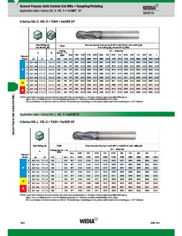
General Purpose Solid Carbide End Mills • Roughing/Finishing
™
Application Data • Series I4B..S I4B..R • VariMill GP
Series I4B..S I4B..R • TiAlN • VariMill GP
Side Milling (A) TiAlN Recommended feed per tooth (IPT = inch/th) for side milling (A).
and Slotting (B) For slotting (B), reduce IPT by 20%.
Cutting D1 — Diameter
A B Speed — vc
SFM frac. 1/64 1/32 1/16 5/64 3/32 1/8 3/16 1/4 5/16 3/8 1/2 5/8 3/4 1
Material
Group ap ae ap min max dec. .0156 .0313 .0625 .0781 .0938 .1250 .1875 .2500 .3125 .3750 .5000 .6250 .7500 1.0000
0 Ap1 max 0.1 x D 0.5 x D 490 – 660 IPT .0001 .0002 .0004 .0005 .0007 .0009 .0013 .0018 .0023 .0027 .0034 .0039 .0044 .0049
1 Ap1 max 0.1 x D 0.5 x D 490 – 660 IPT .0001 .0002 .0004 .0005 .0007 .0009 .0013 .0018 .0023 .0027 .0034 .0039 .0044 .0049
P 2 Ap1 max 0.1 x D 0.5 x D 460 – 620 IPT .0001 .0002 .0004 .0005 .0007 .0009 .0013 .0018 .0023 .0027 .0034 .0039 .0044 .0049
3 Ap1 max 0.1 x D 0.5 x D 390 – 520 IPT .0001 .0002 .0004 .0004 .0005 .0007 .0011 .0015 .0020 .0023 .0029 .0034 .0039 .0045
4 Ap1 max 0.1 x D 0.5 x D 300 – 490 IPT .0001 .0002 .0003 .0004 .0005 .0007 .0010 .0014 .0017 .0020 .0026 .0030 .0034 .0039
1 Ap1 max 0.1 x D 0.5 x D 300 – 380 IPT .0001 .0002 .0004 .0004 .0005 .0007 .0011 .0015 .0020 .0023 .0029 .0034 .0039 .0045
M
2 Ap1 max 0.1 x D 0.5 x D 200 – 260 IPT .0001 .0001 .0003 .0004 .0004 .0006 .0009 .0012 .0016 .0018 .0023 .0027 .0031 .0036
1 Ap1 max 0.1 x D 0.5 x D 390 – 490 IPT .0001 .0002 .0004 .0005 .0007 .0009 .0013 .0018 .0023 .0027 .0034 .0039 .0044 .0049
K
2 Ap1 max 0.1 x D 0.5 x D 360 – 460 IPT .0001 .0002 .0004 .0004 .0005 .0007 .0011 .0015 .0020 .0023 .0029 .0034 .0039 .0045
General Purpose Solid Carbide End Mills Application Data • Series I4B..L I4B..X • VariMill GP
NOTE: Lower value of cutting speed is used for high stock removal applications or for higher hardness (machinability) within group.
Higher value of cutting speed is used for fi nishing applications or for lower hardness (machinability) within group.
Above parameters are based on ideal conditions. For smaller taper machining centers, please adjust parameters accordingly on >1/2" diameter.
Series I4B..L I4B..X • TiAlN • VariMill GP
Side Milling (A) TiAlN Recommended feed per tooth (IPT = inch/th) for side milling (A).
D1 — Diameter
Cutting Speed — vc
A
SFM frac. 3/32 1/8 3/16 1/4 5/16 3/8 1/2 5/8 3/4 1
Material
Group ap ae min max dec. .0938 .1250 .1875 .2500 .3125 .3750 .5000 .6250 .7500 1.0000
0 Ap1 max 0.1 x D 490 – 660 IPT .0007 .0009 .0013 .0018 .0023 .0027 .0034 .0039 .0044 .0049
1 Ap1 max 0.1 x D 490 – 660 IPT .0007 .0009 .0013 .0018 .0023 .0027 .0034 .0039 .0044 .0049
P 2 Ap1 max 0.1 x D 460 – 620 IPT .0007 .0009 .0013 .0018 .0023 .0027 .0034 .0039 .0044 .0049
3 Ap1 max 0.1 x D 390 – 520 IPT .0005 .0007 .0011 .0015 .0020 .0023 .0029 .0034 .0039 .0045
4 Ap1 max 0.1 x D 300 – 490 IPT .0005 .0007 .0010 .0014 .0017 .0020 .0026 .0030 .0034 .0039
1 Ap1 max 0.1 x D 300 – 380 IPT .0005 .0007 .0011 .0015 .0020 .0023 .0029 .0034 .0039 .0045
M
2 Ap1 max 0.1 x D 200 – 260 IPT .0004 .0006 .0009 .0012 .0016 .0018 .0023 .0027 .0031 .0036
1 Ap1 max 0.1 x D 390 – 490 IPT .0007 .0009 .0013 .0018 .0023 .0027 .0034 .0039 .0044 .0049
K
2 Ap1 max 0.1 x D 360 – 460 IPT .0005 .0007 .0011 .0015 .0020 .0023 .0029 .0034 .0039 .0045
NOTE: Lower value of cutting speed is used for high stock removal applications or for higher hardness (machinability) within group.
Higher value of cutting speed is used for fi nishing applications or for lower hardness (machinability) within group.
Above parameters are based on ideal conditions. For smaller taper machining centers, please adjust parameters accordingly on >1/2" diameter.
N30 widia.com
N030 N031 Mi h REBRANDN
lP
WID M
i
V
G
16 S lidE dMilli
L WID_Master16_SolidEndMilling_GeneralPurpose_N030_N031_Minch_REBRAND.indd 30 b 13 20157 32AM 11/13/15 7:36 AM