
Page 1913 - Master Catalog 2017, Inch
P. 1913
High-Performance Thread Mills
CNC Programming Instructions
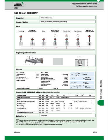
Drill Thread Mill GTM31
Preparation Drilling of thread hole
Process Principle Drilling, countersinking, thread milling (climb milling)
Cycle
Drilling and Run-in loop for Returning to
Positioning Raise Thread milling Run-out loop
countersinking thread milling positioning level
Required Specification Values
Example
Size — M10-6H Tool — GTM31 V • 1000
Thread diameter D .........................................10mm Catalog number ....................................................GTM315005 N= c d • / S = 9709
Pitch .............................................................1,5mm Number of teeth Z ..................................................................2 1
Core hole diameter D ..................................8,5mm Tool diameter d ..........................................................8,2mm*
1 1 1 2427 (drilling,
s
Material — Gray cast iron Tool radius compensation k .....................................0,1mm** v =f • n F = countersinking)
b
2
Tool radius to be programmed ...................................4mm***
Grade — WU12PV
Countersink depth l .................................................19,11mm 1942
s
Cutting speed v .....................................................250 m/min v =f • Z • n F = (contour)
z
f
c
Feed (countersinking) f ..........................................0,25 mm/U
s
Feed (milling) f ..................................................0,1 mm/tooth v contour • (D-d ) F = 350
z
v = f 1 (center point)
f
*(measured on the cutting part) **(0.01 x D) ***(1/2 d - k) D High-Performance Thread Mills
1
Program to DIN 66025 (climb milling, on the contour, incremental)
2
Positioning the tool N 10 G 54 G 90 G 00 X… Y… Z 2 S 9709 T01 M03
Drilling and countersinking N 20 G 91 G 01 Z-21.110 F 2427 (drill, countersink)
Raise N 30 G 01 Z 0.500
Moving sideways to the starting point N 40 G 41 Y-4.250 F 971 (milling, 1/2 contour) [F 175] 3 (1/2 center point)
Run-in loop in arc N 50 G 03 X 0 Y 9.250 Z 0.750 I 0 J 4.625
Thread milling N 60 G 03 X 0 Y 0 Z 1.500 I 0 J -5.000
Run-out loop in arc N 70 G 03 X 0 Y-9.250 Z 0.750 I 0 J- 4.625 F1942 [F 350] 3 (center point)
Exit N 80 G 00 G 40 X 0 Y 4.250
Retracting tool to positioning level N 90 G 90 Z 2
Cutting time t 2.3 seconds
h
NOTES:
1 The cutter radius measured over the tooth crests of the threaded part must be reduced by the amount of the cutter radius compensation. This is necessary to achieve a depth of cut to the middle
of the 6H/ISO2 nut tolerance. Please note, however, that this also depends on the radial deflection of the tool (tensile strength of the material, projecting length of the tool).
2 The cutter radius to be programmed is normally included in the tool memory.
3 The feed values in brackets must be used for controllers, which do not calculate the center point feed themselves.
widia.com W215
10/30/15 2:47 PM
WID_Master16_Taps_W214_W215_Minch_REBRAND.indd 215 L V i WID M 16 T W214 W215 Mi h REBRANDO b 23 20159 39AM