
Page 624 - Master Catalog 2017, Inch
P. 624
Ranger
™
Technical Information
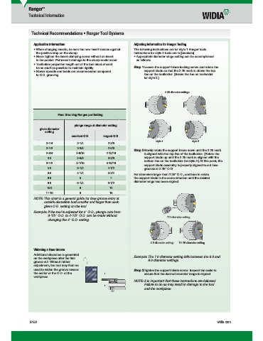
Technical Recommendations • Ranger Tool Systems
Application Information: Adjusting Information for Ranger Tooling
• When changing inserts, be sure the new insert locates against The following instructions are for style 1 Ranger tools.
the positive stop on the clamp. Instructions for style 2 tools are in [brackets].
• Never tighten the insert clamping screw without an insert • Appropriate diameter range setting can be accomplished
in the pocket. Permanent damage to the clamp could occur. as follows:
• Toolholder projection length out of the tool block should
be as short as possible to maintain rigidity. Step 1 Loosen the support blade locking screw and rotate the
• Slower speeds and feeds are recommended compared support blade so that the 2.25 mark is above the top
to O.D. grooving. line on the toolholder. [Below the line on toolholder
for style 2.]
2.25 diameter settings
Face Grooving Ranges per Setting
plunge range at diameter setting
given diameter
setting
smallest O.D. largest O.D.
style 1 style 2
2-1/4 2-1/4 2-3/8
2-1/2 2-3/8 2-5/8
Step 2 Slowly rotate the support blade down until the 2.25 mark
2-3/4 2-9/16 2-15/16 is aligned with the top line of the toolholder. [Rotate the
3.0 2-5/8 3-3/8 support blade up until the 2.25 mark is aligned with the
bottom line on the toolholder for style 2.] At this point, the
3-1/2 3-1/16 3-15/16
support blade assembly is properly aligned to cut face
4.0 3-1/2 4-1/2 grooves at 2.25" O.D.
5.0 4-1/4 5-3/4
For diameters larger than 2.25" O.D., continue to rotate
6.0 5 7 the support blade in the same direction until the desired
diameter range has been aligned.
8.0 6-1/2 9-1/2
10.0 8 11
11-16 9 16
NOTE: This chart is a general guide for face groove entry at
outside diameters both smaller and larger than each
given O.D. setting on the tool.
Example: If the tool is adjusted for 4" O.D., plunge cuts from
3-1/2" O.D. to 4-1/2" O.D. can be made without 7.0 diameter setting
changing the 4" O.D. setting.
4.0 diameter setting 11–16 diameter setting
Widening a Face Groove
Additional clearance is generated Example: The 7.0 diameter setting falls between the 6.0 and
on the workpiece after the fi rst
groove cut. Without further 8.0 diameter settings.
adjustment, the tool may then be
used to widen the groove toward Step 3 Tighten the support blade screw. Inspect the scale to
the center or the O.D. of the ensure that the desired diameter range is aligned.
workpiece.
NOTE: It is important that these instructions are followed.
Failure to do so may result in damage to the tool
and the workpiece.
E152 widia.com
i
G
V
16 T
&C Off E152 E153 Mi
WID M
i
i
L WID_Master16_Turning_Grooving&CutOff_E152_E153_Minch_REBRAND.indd 152 h REBRANDN b 10 20157 49AM 11/10/15 11:15 AM