
Page 7 - 1.Antminer L3+ Hash Board Repair Guide EN
P. 7
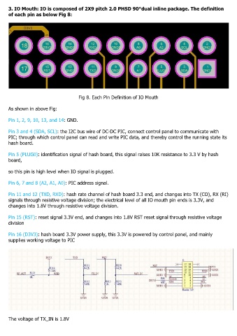
3. IO Mouth: IO is composed of 2X9 pitch 2.0 PHSD 90°dual inline package. The definition
     of each pin as below Fig 8:


                                         Fig 8. Each Pin Definition of IO Mouth

     As shown in above Fig:


     Pin 1, 2, 9, 10, 13, and 14: GND.

     Pin 3 and 4 (SDA, SCL): the I2C bus wire of DC-DC PIC, connect control panel to communicate with
     PIC; through which control panel can read and write PIC data, and thereby control the running state its
     hash board.


     Pin 5 (PLUG0): identification signal of hash board, this signal raises 10K resistance to 3.3 V by hash
     board,

     so this pin is high level when IO signal is plugged.


     Pin 6, 7 and 8 (A2, A1, A0): PIC address signal.

     Pin 11 and 12 (TXD, RXD): hash rate channel of hash board 3.3 end, and changes into TX (CO), RX (RI)
     signals through resistive voltage division; the electrical level of all IO mouth pin ends is 3.3V, and
     changes into 1.8V through resistive voltage division.

     Pin 15 (RST): reset signal 3.3V end, and changes into 1.8V RST reset signal through resistive voltage
     division


     Pin 16 (D3V3): hash board 3.3V power supply, this 3.3V is powered by control panel, and mainly
     supplies working voltage to PIC


     The voltage of TX_IN is 1.8V