
Page 294 - 2006 HARLEY FLSTCI SERVICE MANUAL
P. 294
5.21 5-75
DIAGNOSTICS Diagnostic Tips Once the engine is started, the ET voltage should rise steadily. Check the following conditions: Poor connection: Inspect ECM and harness connector ● [78] for backed out terminals, improper mating, broken locks, improperly formed or damaged terminals, poor ter- minal-to-wire connection and damaged harness. Perform 5.8 WIGGLE TEST to locate intermittents: If ● connections and harness check out OK, use a DVOM to check the engine temperature sensor voltage reading while moving related connectors and wiring harness. If the failure is induced, the engine temperature sensor volt
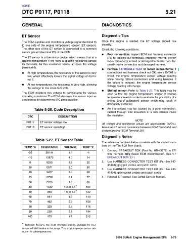
TEMP °F VOLTAGE -4 4.4 14 4.0 32 3.5 50 3.0 68 2.4 77 2.1 86 1.8 104 1.3 or 4.1* 122 1.0 or 3.7* 140 3.3 158 2.9 176 2.5 194 2.1 212 1.7
DESCRIPTION
DTC P0117, P0118 The ECM supplies and monitors a voltage signal (terminal 6) to one side of the engine temperature sensor (ET sensor). The other side of the ET sensor is connected to a common sensor ground (terminal 26) of the ECM. The ET sensor is a thermistor device, which means that at a specific temperature it will have a specific resistance across its terminals. As this resistance varies, so does the voltage At high temperatures, the resistance of the sensor is very low, which effectively lowers the signal voltage on termi- At low temperatures, the resistance is very high, allowing the voltage to rise close
HOME GENERAL ET Sensor (terminal 6). ● nal 6. ● DTC P0117 P0118 TEMP °C -20 -10 0 10 20 25 30 40 50 60 70 80 90 100 *