
Page 96 - NEW Armstrong Book - 2
P. 96
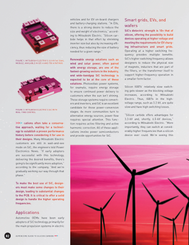
                                  FIGURE 1: MITSUBISHI ELECTRIC’S 3.3-KV SiC DUAL MODULE, AVAILABLE IN 325-A AND 750-A RATINGS
FIGURE 2: MITSUBISHI ELECTRIC’S SiC WITH REAL-TIME CONTROL
cations often take a conserva- tive approach, waiting for a technol- ogy to establish a proven performance history before considering it for use in their designs. Many Mitsubishi Electric customers are still in wait-and-see mode on SiC, the engineers told Power Electronics News. “If early adopters are successful with this technology, delivering the desired benefits, there’s going to be significantly more adoption,” according to the company. “And we’re gradually working our way through that phase.”
To make the best use of SiC, design- ers must make some changes to their design, leading to substantial changes to the PCB. It is critical to offer a solid design to handle the higher operating frequencies.
Applications
Automotive OEMs have been early adopters of SiC technology, primarily for the main propulsion systems in electric
vehicles and for EV on-board chargers and battery-charging stations. “In EVs, there is a strong desire to reduce the size and weight of electronics,” accord- ing to Mitsubishi Electric. “Silicon car- bide helps in that effort by shrinking inverter size but also by increasing effi- ciency, thus reducing the size of battery needed for a given range.”
Renewable energy solutions such as wind and solar power, often paired with energy storage, are one of the fastest-growing sectors in the industry, and wide-bandgap SiC technology is expected to be at the core of these solutions. Photovoltaic power systems, for example, require energy storage to ensure continued power delivery to customers when the sun isn’t shining. Those storage systems require convert- ers and inverters, and SiC is an excellent candidate for those power-conversion stages. As more communities turn to alternative energy sources, power flow requires special attention. This func- tion requires active filtering and active harmonic correction. All of these appli- cations involve power semiconductors and provide opportunities for SiC.
Smart grids, EVs, and
wafers
SiC’s dielectric strength is 10× that of silicon, offering the possibility to build devices operating at higher voltage and meeting the requirements for EV charg- ing infrastructure and smart grids. Operating at a higher switching fre- quency provides multiple benefits. SiC’s higher switching frequency allows designers to reduce the physical size of magnets, inductors that are part of the filters, or the transformer itself to support higher-frequency operation in a smaller form factor.
Silicon IGBTs’ relatively slow switch- ing gets slower as the blocking voltage increases, according to Mitsubishi Electric. Thus, IGBTs in the high- voltage range, such as 3.3 kV, are quite slow and have high switching losses.
“Silicon carbide offers advantages for 3.3-kV and, shortly, 6.5-kV devices,” according to Mitsubishi Electric. “More importantly, they can switch at consid- erably higher frequencies than a silicon device ever could. We’re seeing this
      82
ASPENCORE GUIDE TO SILICON CARBIDE
