
Page 126 - KA Sensors 2020 Motorsport Catalog_Neat
P. 126
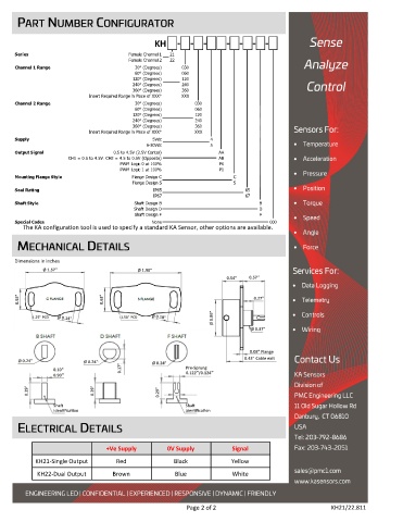
KH - - - - - - -
Series Female Channel 1 21
Female Channel 2 22
Channel 1 Range 30° (Degrees) 030
60° (Degrees) 060
120° (Degrees) 120
240° (Degrees) 240
360° (Degrees) 360
Insert Required Range in Place of XXX° XXX
Channel 2 Range 30° (Degrees) 030
60° (Degrees) 060
120° (Degrees) 120
240° (Degrees) 240
360° (Degrees) 360
Insert Required Range in Place of XXX° XXX
Supply 5Vdc 4
6-30Vdc 5
Output Signal 0.5 to 4.5V (2.5V Center) AA
CH1 = 0.5 to 4.5V. CH2 = 4.5 to 0.5V (Opposite) AB
PWM Logic 0 at 100% P0
PWM Logic 1 at 100% P1
Mounting Flange Style Flange Design C C
Flange Design S S
Seal Rating IP65 65
IP67 67
Shaft Style Shaft Design B B
Shaft Design D D
Shaft Design F F
Special Codes None 000
The KA configuration tool is used to specify a standard KA Sensor, other options are available.
Dimensions in inches
Ø 1.57" Ø 1.90"
0.54" 0.57"
0.55" 0.63" 0.27"
Ø 0.89"
1.25" PCD 1.50" PCD
Ø 0.37"
0.08" Flange
0.43" Cable exit
Ø 0.24" Ø 0.24" Ø 0.24"
0.10" 0.17" Pre-Sprung
0.90" 0.122"/0.124"
0.29" 0.29" 0.29"
Shaft Shaft
Identification Identification
+Ve Supply 0V Supply Signal
KH21-Single Output Red Black Yellow
KH22-Dual Output Brown Blue White
Page 2 of 2 KH21/22.811