
Page 165 - Driving Commercial Vehicles Manual+
P. 165
driving commercial vehicles
The treadle (pedal) of a foot valve has a springy feel that is quite different
fast fact from the feel of a hydraulic brake pedal of a car. For one thing, you really
don’t have to press harder on a foot valve to apply more braking force —
The maximum brake you simply have to press it down a bit farther. If the foot valve is held in one
application will not position, the air pressure delivered to the brake system will remain constant.
exceed the pressure in the
reservoirs. Releasing the foot valve allows the application air to be exhausted through
the assembly’s exhaust ports to the atmosphere.
For example, if reservoir
pressure is 80 p.s.i. (552 kPa), In effect, it is a foot-controlled pressure regulator. It’s the device that allows
the maximum brake you to select any application pressure needed to make a gentle, or a very
application you could make rapid stop.
wouldn’t exceed 80 p.s.i.
A unique feature of a foot control valve is the ability to maintain the
application pressure that you’ve chosen, even if there are small leaks
downstream from the foot valve. You need only to maintain the treadle
position and the foot valve will momentarily open, replenish any air that has
been lost, and then close — all automatically.
How air brakes work
Brakes applied
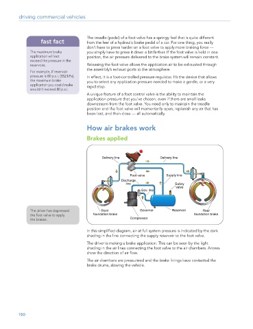
The driver has depressed
the foot valve to apply
the brakes.
In this simplified diagram, air at full system pressure is indicated by the dark
shading in the line connecting the supply reservoir to the foot valve.
The driver is making a brake application. This can be seen by the light
shading in the air lines connecting the foot valve to the air chambers. Arrows
show the direction of air flow.
The air chambers are pressurized and the brake linings have contacted the
brake drums, slowing the vehicle.
150