
Page 59 - Draft 2023 2024 CDL Manual w Modernization Info
P. 59
SECTION 6: COMBINATION VEHICLES
• Tighten in both the lock screws (2, 2a) to • Loosen safety lock screw (2a) and remove Step 3. Install Safety Pin and Clip
gether with their relative self-locking nuts (12, safety lock screw (2) together with its self • Install safety pin and clip. (Fig. B)
12a) at a 350 to 400 Nm torque wrench setting. locking nut (12).
Step 5. Adjust the Adjustment Screw Step 3. Rotate Safety Cover Bar and Lift
• Adjust the adjustment screw (3) until a 0.3 - Trailer Drawbeam
0.5 mm vertical clearance between the guard • Rotate the safety cover bar (4) outwards so
disk (13) and the ball cup (6) is reached. Lock that it is completely open.
setting with counter nut (11).
• Lift the trailer drawbeam until the drawbar
coupling ball (5) is fully visible, then travel
forward with the trailer very slowly.
• Rotate the safety cover bar inwards (4) until
it lodges back in its housing.
Step 4. Lock Safety Screw and Tighten Figure B
Self-Locking Nut
• Fit in safety lock screw (2) and tighten in self- 6.5 - lnspectin9 a
locking nut (12). Combination Vehicle
6.4.7 -Coupling a Gooseneck Hitch Use the seven-step inspection procedure de
• If you are hooking up a Gooseneck or a fifth scribed in Section 2 to inspect your combination
vehicle. There are more things to inspect on a
wheel hitch, the procedure is a little different
from a receiver and ball, but it is not more combination vehicle than on a single vehicle.
(For example, tires, wheels, lights, reflectors,
difficult. etc.) However, there are also some new things
to check. These are discussed below.
Step 1. Open the Latch and Lubricate the
Gooseneck Ball 6.5.1 -Additional Things to Check
• Open the clamp latch on the Gooseneck During a Walk-around Inspection
coupler. Do these checks in addition to those already
• In the event that the safety cover bar (4) will • Make sure that the Gooseneck ball is properly listed in Section 2.
not perfectly lodge into its seating appropri lubricated.
ately, travel is strictly forbidden. Coupling S y stem Areas
Step 2. Position Coupler and Latch the • Check fifth wheel (lower).
Clamp » Securely mounted to frame.
» No missing or damaged parts.
• Position the trailer's coupler directly over » Enough grease.
the ball and lower the Gooseneck trailer into
position and latch the clamp. » No visible space between upper and lower
fifth wheel.
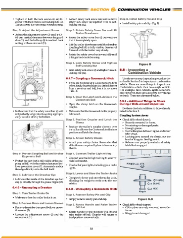
» Locking jaws around the shank, not the
Step 3. Attach Safety Chains head of kingpin. See Figure 6.8.
• Attach your safety chains. Remember that » Release arm properly seated and safety
all trailers are required by law to have safety latch/lock engaged.
chains.
Step 6. Protect Coupling Ball and Anchor Step 4. Connect Trailer Light Wiring --- ---
Edge onto Ball • Connect your trailer light wiring to your ve
• Protect the part that is still visible of the cou hicle's connector.
pling ball (5) with the rubber dust proof bel Kingpin =!> g
lows protection cover (7). Accurately anchor • Check all of your lights, including your brake
lights.
the edge directly onto the ball itself.
Step 7. Lubricate the Drawbar Eye Step 5. Lower and Stow the Trailer Jacks
• Lubricate the inside of the drawbar eye ball • Completely lower and stow the trailer jacks,
cup (6) directly through the grease nipple (18). allowing the weight to settle onto the tow ¢:J BASE
vehicle. ¢:J SHANK
6.4.6 - Uncoupling a Drawbar
6.4.8 - Uncoupling a Gooseneck Hitch ¢:J HEAD
Kingpin
Step 1. Turn Trailer Brake On Step 1. Remove Safety Pin and Clip
• Make sure that the trailer brake is on.
• Simply remove safety pin and clip. Figure 6.8
Step 2. Remove Cover and Loosen Screws Step 2. Rotate Handle and Raise Trailer • Check fifth wheel (upper).
• Removethe rubberdustproofbellows protec- Off Ball » Glide plate securely mounted to trailer
tion cover (7). • Rotate handle to this position (Fig. B) and frame.
• Loosen the adjustment screw (3) and the raise trailer off ball. Coupler will return to » Kingpin not damaged.
counter nut (11). load position automatically.
59