
Page 22 - MOTER BOOK
P. 22
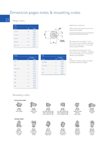
Dimension pages notes & mounting codes


       22       Page notes


                 Shaft                                                           All dimensions in millimetres
                 Dim D           Tol   Limits                        GD          Cable entry can be arranged in any one of four
                 11 to 14        j6    +0.008                            F       positions at 90° intervals
                                       –0.003                                    Dimensions should not be used for installation
                 19 to 28        j6    +0.009        D                           purposes unless specially endorsed
                                       –0.004
                 38 to 48        k6    +0.018
                                       +0.002                         TAPPED
                 55 to 80        m6    +0.030                 G       HOLE DH    B5 mounted motors have suffix ‘-D’ in the
                                       +0.011                                    frame reference, eg A-DA132MA-D and B3/B5
                 85 to 110       m6    +0.035                                    mounted motors have suffix ‘-H’ in the frame
                                       +0.013                                    reference, eg A-DA132MA-H

                                                                                 B14 mounted motors have suffix ‘C’ in the
                                                                                 frame reference, eg A-DA132MA-C and B3/B14
                                                                                 mounted motors have suffix ‘-H’ in the frame
                  Flange                          Face                           reference, eg A-DA132MA-H
                                   IEC 60072                        IEC 60072
                  Dim N          Tol   Limits     Dim N          Tol   Limits    Note
                  110            j6    +0.013     70 and 80      j6    +0.012    355LB frame and above, flange only available
                                       –0.009                          –0.007    when B35 mounted (foot & flange).
                  130            j6    +0.014     95 and 110     j6    +0.013
                                       –0.011                          –0.009
                  230 to 250     j6    +0.016     130            j6    +0.014
                                       –0.013                          –0.011
                  300            j6    +0.016     230            j6    +0.016
                                       -0.016                          –0.013
                  350            j6    +0.018
                                       -0.018
                  450            j6    +0.020
                                       -0.020
                  550            j6    +0.022
                                       -0.022
                  680            js6   +0.025
                                       -0.025


                Mounting codes


                  Horizontal shaft:


                     IM B3            IM B5            IM B6            IM B7            IM B8           IM B14
                     IM 1001         IM 3001          IM 1051          IM 1061          IM 1071          IM 3601
                   foot mounted     flange at DE  foot wall mounted with  foot wall mounted with  ceiling mounted  face at DE
                                      no feet      feet on left-hand side  feet on right-hand side  with feet  no feet
                                                  when viewed from DE  when viewed from DE  above motor

                  Vertical shaft:


                     IM V1            IM V3            IM V5            IM V6           IM V18           IM V19
                     IM 3011         IM 3031          IM 1011          IM 1031          IM 3611          IM 3631
                   flange at DE     flange at DE     vertical foot    vertical foot    face at DE       face at DE
                    shaft down        shaft up       wall mounted     wall mounted     shaft down        shaft up
                     no feet          no feet         shaft down       shaft up          no feet         no feet